NOTE:
Systems shipped with an aluminum chassis include two RF metal wall brackets that are installed on the left and right
sides of the palm rest.
Steps
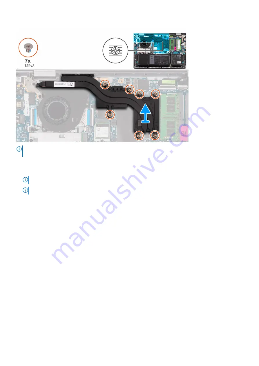
1. Loosen the seven (M2x3) captive screws that secure the heat sink to the system board.
NOTE:
Loosen the captive screws in the reverse sequential order mentioned on the heat sink [7>6>5>4>3>2>1].
NOTE:
The number of screws varies depending on the configuration ordered.
2. Lift the heat sink from the system board.
Installing the discrete heat sink
Prerequisites
If you are replacing a component, remove the existing component before performing the installation process.
About this task
The following images indicate the location of the discrete heat sink and provide a visual representation of the installation
procedure.
Removing and installing components
35
Summary of Contents for P152G
Page 14: ...About this task 14 Removing and installing components ...
Page 16: ...About this task 16 Removing and installing components ...
Page 45: ...Removing and installing components 45 ...
Page 50: ...50 Removing and installing components ...


