background image

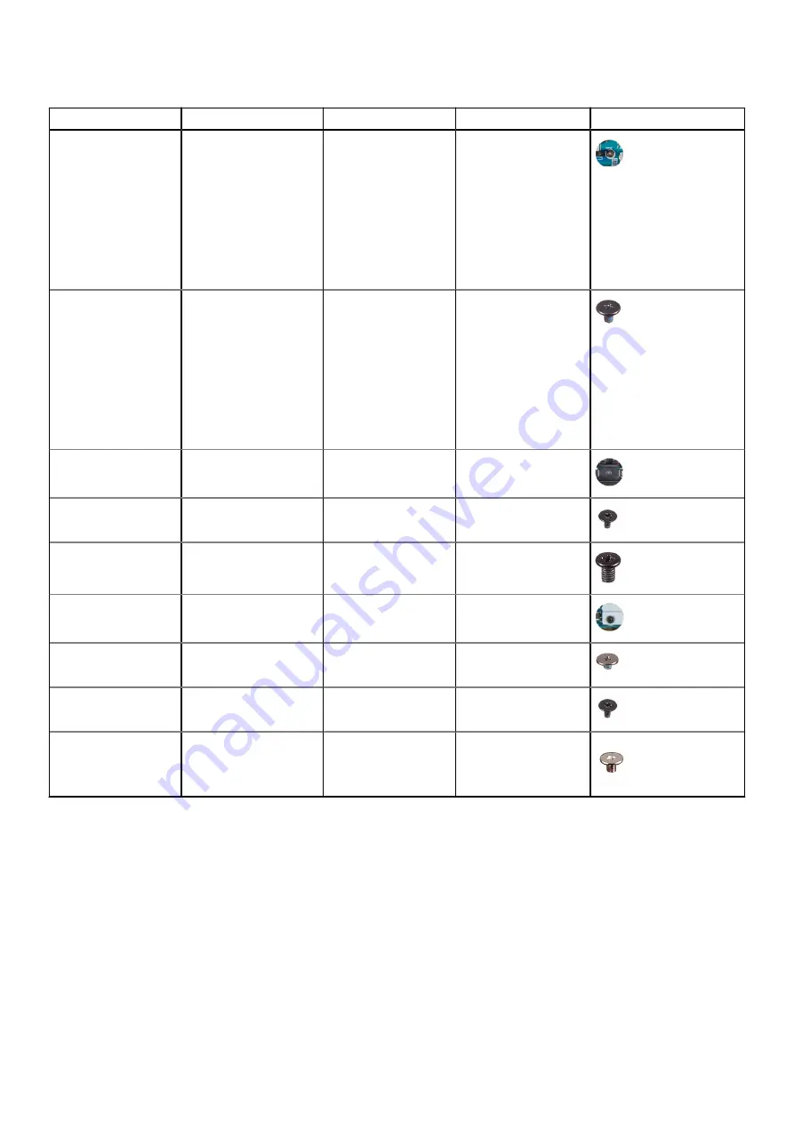
Table 1. Screw list (continued)

Component

Secured to

Screw type

Quantity

Screw image

Heat-sink and fan
assembly (in
computers shipped
with computers
shipped with 11

th

Generation Intel Core
i5-1135G7 processor
or 11

th

 Generation Intel

Core i7-1165G7
processor)

System board

M2x3 (captive)

4

Heat-sink and fan
assembly (in
computers shipped
with computers
shipped with 11

th

Generation Intel Core
i5-1135G7 processor
or 11

th

 Generation Intel

Core i7-1165G7
processor)

System board

M1.6x2.5

4

Display-assembly
cable bracket

System board

M1.6x2 (captive)

3

Display-assembly
cable holder

System board

M1.2x2

3

Display-assembly
hinges

Palm-rest and keyboard
assembly

M2.5x4.5

6

Wireless-card bracket

System board

M1.6x2.3 (captive)

1

System board

Palm-rest and keyboard
assembly

M1.6x1.5

4

System board

Palm-rest and keyboard
assembly

M1.2x2

3

System board

Palm-rest and keyboard
assembly

M1.4x4

4

Major components of XPS 13 9310

The following image shows the major components of XPS 13 9310.

Removing and installing components

9

Summary of Contents for P117G

Page 1: ...XPS 13 9310 Service Manual Regulatory Model P117G Regulatory Type P117G002 September 2020 Rev A00 ...

Page 2: ...ential damage to hardware or loss of data and tells you how to avoid the problem WARNING A WARNING indicates a potential for property damage personal injury or death 2020 Dell Inc or its subsidiaries All rights reserved Dell EMC and other trademarks are trademarks of Dell Inc or its subsidiaries Other trademarks may be trademarks of their respective owners ...

Page 3: ... 2230 solid state drive 17 Installing the M 2 2230 solid state drive 18 Removing the M 2 2280 solid state drive 19 Installing the M 2 2280 solid state drive 20 Fans 22 Removing the fans 22 Installing the fans 23 Heat sink 25 Removing the heat sink 25 Installing the heat sink 25 Heat sink and fan assembly 26 Removing the heat sink and fan assembly 26 Installing the heat sink and fan assembly 27 Dis...

Page 4: ...t Sequence 45 One time boot menu 46 System setup options 46 Clearing CMOS settings 57 Clearing BIOS System Setup and System passwords 57 Chapter 5 Troubleshooting 58 Recovering the operating system 58 SupportAssist On board Diagnostics 58 System diagnostic lights 58 Flea power release 59 WiFi power cycle 60 Chapter 6 Getting help and contacting Dell 61 4 Contents ...

Page 5: ...r computer WARNING Before working inside your computer read the safety information that is shipped with your computer For more safety best practices see the Regulatory Compliance home page at www dell com regulatory_compliance WARNING Disconnect your computer from all power sources before opening the computer cover or panels After you finish working inside the computer replace all covers panels an...

Page 6: ... to the damage The weakened trace may take weeks or months to melt and in the meantime may cause degradation of memory integrity intermittent memory errors etc The more difficult type of damage to recognize and troubleshoot is the intermittent also called latent or walking wounded failure Perform the following steps to prevent ESD damage Use a wired ESD wrist strap that is properly grounded The us...

Page 7: ... 30 centimeters away from sensitive parts before physically handling any hardware components ESD Packaging All ESD sensitive devices must be shipped and received in static safe packaging Metal static shielded bags are preferred However you should always return the damaged part using the same ESD bag and packaging that the new part arrived in The ESD bag should be folded over and taped shut and all...

Page 8: ...stored when the component is replaced NOTE Some computers have magnetic surfaces Ensure that the screws are not left attached to such surfaces when replacing a component NOTE Screw color may vary with the configuration ordered Table 1 Screw list Component Secured to Screw type Quantity Screw image Base cover Palm rest and keyboard assembly M2x3 Torx 5 8 Battery Palm rest and keyboard assembly M1 6...

Page 9: ...or or 11th Generation Intel Core i7 1165G7 processor System board M1 6x2 5 4 Display assembly cable bracket System board M1 6x2 captive 3 Display assembly cable holder System board M1 2x2 3 Display assembly hinges Palm rest and keyboard assembly M2 5x4 5 6 Wireless card bracket System board M1 6x2 3 captive 1 System board Palm rest and keyboard assembly M1 6x1 5 4 System board Palm rest and keyboa...

Page 10: ...eat sink and fan assembly in computers shipped with 11th Generation Intel Core i5 1135G7 or 11th Generation Intel Core i7 1165G7 processor 5 Left antenna 6 System board 7 Left speaker 8 Palm rest and keyboard assembly 9 Display assembly 10 Right speaker 11 Display cable bracket 12 Right antenna 13 Right fan in computers shipped with 11th Generation Intel Core i3 1115G4 processor NOTE The right fan...

Page 11: ...coverages purchased by the customer Contact your Dell sales representative for purchase options Base cover Removing the base cover Prerequisites 1 Follow the procedure in Before working inside your computer About this task The following images indicate the location of the base cover and provide a visual representation of the removal procedure Removing and installing components 11 ...

Page 12: ...12 Removing and installing components ...

Page 13: ... rotate the base cover from bottom to top to remove it from the palm rest and keyboard assembly NOTE The pins at the bottom of the base cover for grounding the antennas and the audio board are fragile Place the base cover on a clean surface to avoid damage to the pins NOTE The following steps are applicable only if you want to further remove any other component from your computer 4 Peel the tape t...

Page 14: ...component remove the existing component before performing the installation procedure About this task The following images indicate the location of the base cover and provide a visual representation of the installation procedure 14 Removing and installing components ...

Page 15: ...ext steps 1 Follow the procedure in After working inside your computer Battery Lithium ion battery precautions CAUTION Exercise caution when handling Lithium ion batteries Discharge the battery completely before removing it Disconnect the AC power adapter from the system and operate the computer solely on battery power the battery is fully discharged when the computer no longer turns on when the p...

Page 16: ...ies from www dell com or authorized Dell partners and resellers Removing the battery Prerequisites 1 Follow the procedure in Before working inside your computer 2 Remove the base cover About this task The following image indicates the location of the battery and provides a visual representation of the removal procedure Steps 1 Peel off the tape and disconnect the battery cable from the system boar...

Page 17: ...r working inside your computer Solid state drive Removing the M 2 2230 solid state drive Prerequisites 1 Follow the procedure in Before working inside your computer CAUTION Solid state drives are fragile Exercise care when handling the solid state drive CAUTION To avoid data loss do not remove the solid state drive while the computer is in sleep or on state 2 Remove the base cover About this task ...

Page 18: ...the solid state drive slot on the system board Installing the M 2 2230 solid state drive Prerequisites If you are replacing a component remove the existing component before performing the installation procedure CAUTION Solid state drives are fragile Exercise care when handling the solid state drive CAUTION To avoid data loss do not remove the solid state drive while the computer is in sleep or on ...

Page 19: ...em board 3 Insert the notch on the solid state drive shield into a slot on the peg on the system board 4 Replace the screw M2x3 that secures the M 2 2230 solid state drive shield to the system board 5 Route the antenna cable through the routing guides along the solid state drive shield Next steps 1 Install the base cover 2 Follow the procedure in After working inside your computer Removing the M 2...

Page 20: ...location of the M 2 2280 solid state drive and provides a visual representation of the removal procedure Steps 1 Remove the antenna cable from the routing guides along the edge of the solid state drive shield 2 Remove the screw M2x3 that secures the M 2 2280 solid state drive shield to the system board 3 Slide and lift the M 2 2280 solid state drive off the solid state drive slot on the system boa...

Page 21: ...location of the M 2 2280 solid state drive and provides a visual representation of the installation procedure Steps 1 Align the notch on the M 2 2280 solid state drive with the tab on solid state drive slot on the system board 2 Slide the M 2 2280 solid state drive into solid state drive slot on the system board 3 Insert the notch on the solid state drive shield into a slot on the peg on the syste...

Page 22: ...fore working inside your computer 2 Remove the base cover About this task NOTE This procedure applies to computers shipped with 11th Generation Intel Core i3 1115G4 processor The following images indicate the location of the fans and provide a visual representation of the removal procedure 22 Removing and installing components ...

Page 23: ...stem board 7 Remove the two screws M1 6x2 5 that secure fan B to the system board 8 Lift fan B off the system board Installing the fans Prerequisites If you are replacing a component remove the existing component before performing the installation procedure About this task NOTE This procedure applies to computers shipped with 11th Generation Intel Core i3 1115G4 processor The following images indi...

Page 24: ... the system board 4 Adhere the tape that secures the fan B cable to the system board 5 Align the screw holes on fan A with the screw holes on the system board 6 Replace the two screws M1 6x2 5 that secure fan A to the system board 7 Connect the fan A cable to the system board 8 Adhere the tape that secures the fan A cable to the system board 24 Removing and installing components ...

Page 25: ...ore you touch it 2 Remove the base cover About this task NOTE This procedure applies to computers shipped with 11th Generation Intel Core i3 1115G4 processor The heat sink and the fans are separate units The following image indicates the location of the heat sink and provides a visual representation of the removal procedure Steps 1 In reverse sequential order as indicated on the heat sink loosen t...

Page 26: ...system board 2 In sequential order as indicated on the heat sink tighten the four captive screws M2x3 that secure the heat sink to the system board Next steps 1 Install the base cover 2 Follow the procedure in After working inside your computer Heat sink and fan assembly Removing the heat sink and fan assembly Prerequisites 1 Follow the procedure in Before working inside your computer CAUTION For ...

Page 27: ...he system board 5 Lift the heat sink and fan assembly off the system board Installing the heat sink and fan assembly Prerequisites If you are replacing a component remove the existing component before performing the installation procedure NOTE This procedure applies to computers shipped with 11th Generation Intel Core i5 1135G7 processor or 11th Generation Intel Core i7 1165G7 processor The heat s...

Page 28: ...m board 4 Connect the fan cables to the system board 5 Adhere the tape that secures the fan cables to the system board Next steps 1 Install the base cover 2 Follow the procedure in After working inside your computer Display assembly Removing the display assembly Prerequisites 1 Follow the procedure in Before working inside your computer 2 Remove the base cover About this task The following images ...

Page 29: ...Removing and installing components 29 ...

Page 30: ...he display assembly cable holder to the palm rest and keyboard assembly 5 Remove the three screws M2 5x4 5 that secure the left hinge to the system board and the palm rest and keyboard assembly 6 Remove the three screws M2 5x4 5 that secure the right hinge to the system board and the palm rest and keyboard assembly 7 Slide the palm rest and keyboard assembly from the display assembly 8 After perfo...

Page 31: ...component remove the existing component before performing the installation procedure About this task The following images indicate the location of the display assembly and provide a visual representation of the installation procedure Removing and installing components 31 ...

Page 32: ...32 Removing and installing components ...

Page 33: ...splay assembly cable holder with the screw holes on the palm rest and keyboard assembly 6 Replace the three screws M1 2x2 that secure the display assembly cable holder to the palm rest and keyboard assembly NOTE Apply gentle torque when tightening the three screws M1 2x2 to avoid damaging the screw threads 7 Connect the camera cable and the display cable to the system board 8 Align the screw holes...

Page 34: ...essor 5 Remove the heat sink for computers shipped with 11th Generation Intel Core i3 1115G4 processor NOTE The system board can be removed or installed together with the heat sink attached This simplifies the procedure and avoids breaking the thermal bond between the system board and the heat sink 6 Remove the heat sink and fan assembly for computers shipped with 11th Generation Intel Core i5 113...

Page 35: ...Removing and installing components 35 ...

Page 36: ...om the system board 7 Disconnect the right speaker cable from the system board 8 Open the latch and disconnect the keyboard cable from the system board 9 Open the latch and disconnect the touchpad cable from the system board 10 Disconnect the left speaker cable from the system board 11 Remove the four screws M1 6x1 5 that secure the system board to the palm rest and keyboard assembly 12 Remove the...

Page 37: ...ny changes you have made to the BIOS using the BIOS setup program You must make the appropriate changes again after you replace the system board About this task The following image indicates the connectors on your system board Figure 2 System board connectors 1 Power button and fingerprint reader cable 2 Touchpad cable 3 Right speaker cable 4 Keyboard cable 5 Left speaker cable The following image...

Page 38: ...38 Removing and installing components ...

Page 39: ...ble to the system board 7 Connect the keyboard cable to the system board and close the latch to secure the cable 8 Connect the touchpad cable to the system board and close the latch to secure the cable 9 Connect the left speaker cable to the system board 10 Route the left and right antenna cables through the routing guides on the palm rest and keyboard assembly toward the wireless card 11 Connect ...

Page 40: ...G7 processor or 11th Generation Intel Core i7 1165G7 processor 6 Install the battery 7 Install the base cover 8 Follow the procedure in After working inside your computer Status light board Removing the status light board Prerequisites 1 Follow the procedure in Before working inside your computer 2 Remove the base cover 3 Remove the battery About this task The following image indicates the status ...

Page 41: ...board is aligned with the peg on the palm rest and keyboard assembly 2 Connect the status light board cable to the keyboard control daughterboard on the palm rest and keyboard assembly and close the latch to secure the cable Next steps 1 Install the battery 2 Install the base cover 3 Follow the procedure in After working inside your computer Palm rest and keyboard assembly Removing the palm rest a...

Page 42: ...rocedure After performing the steps in the pre requisites you are left with the palm rest and keyboard assembly Installing the palm rest and keyboard assembly Prerequisites If you are replacing a component remove the existing component before performing the installation procedure About this task The following image indicates the palm rest and keyboard assembly and provides a visual representation ...

Page 43: ...ard 2 Install the system board 3 Install the display assembly 4 Install the battery 5 Install the base cover NOTE The system board can be installed with the heat sink or the heat sink and fan assembly attached 6 Follow the procedure in After working inside your computer Removing and installing components 43 ...

Page 44: ...rivers and downloads When troubleshooting downloading or installing drivers it is recommended that you read the Dell Knowledge Based article Drivers and Downloads FAQ SLN128938 3 44 Drivers and downloads ...

Page 45: ...k Turn on or restart your computer and press F2 immediately Navigation keys NOTE For most of the System Setup options changes that you make are recorded but do not take effect until you restart the system Table 2 Navigation keys Keys Navigation Up arrow Moves to the previous field Down arrow Moves to the next field Enter Selects a value in the selected field if applicable or follow the link in the...

Page 46: ... the SATA drive number Optical Drive if available SATA Hard Drive if available Diagnostics The boot sequence screen also displays the option to access the System Setup screen System setup options NOTE Depending on this computer and its installed devices the items that are listed in this section may or may not be displayed Table 3 System setup options Overview menu Overview XPS 13 9310 BIOS Version...

Page 47: ...ilable Displays the total computer memory available Memory Speed Displays the memory speed Memory Channel Mode Displays single or dual channel mode Memory Technology Displays the technology that is used for the memory DEVICES Panel Type Displays the Panel Type of the computer Video Controller Displays the integrate graphics information of the computer Video Memory Displays the video memory informa...

Page 48: ... Integrated Devices Date Time Date Sets the computer date in MM DD YYYY format Changes to the date take effect immediately Time Sets the computer time in HH MM SS 24 hour format You can switch between 12 hour and 24 hour clock Changes to the time take effect immediately Camera Enable Camera Enables or disables the camera By default Enable Camera is selected Audio Enable Audio Enables or disables a...

Page 49: ...rated SATA hard drive controller Default AHCI NVMe Storage device is configured for AHCI NVMe mode Storage Interface Displays the information of various onboard drives Port Enablement Enables or disables the M 2 PCIe SSD Default ON Drive Information Displays the information of onboard drives Enable MediaCard Enables to switch all media cards On Off or set the media card to read only state By defau...

Page 50: ...ptively optimized based on your typical battery usage pattern Advanced Configuration Enable Advanced Battery Charge Configuration Enables Advanced Battery Charge Configuration from the beginning of the day to a specified work period Advanced Battery Charged maximizes battery health while still supporting heavy use during the work day Default OFF Peak Shift Enable Peak Shift Enables the computer to...

Page 51: ...ds Default OFF Attestation Enable Enables to control whether the TPM Endorsement Hierarchy is available to the OS Disabling this setting restricts the ability to use the TPM for signature operations Default ON Key Storage Enable Enables to control whether the TPM Endorsement Hierarchy is available to the OS Disabling this setting restricts the ability to use the TPM for storing owner data Default ...

Page 52: ...UEFI boot path from the F12 boot menu Default Always Except Internal HDD Table 11 System setup options Passwords menu Passwords Admin Password Sets Changes or deletes the administrator admin password sometimes called the setup password System Password Sets Changes or deletes the system password Password Configuration Upper Case Letter Enables or disables the requirement for at least one upper case...

Page 53: ...s intact and functioning Default ON NOTE BIOS recovery is designed to fix the main BIOS block and cannot work if the Boot Block is damaged In addition this feature cannot work in the event of EC corruption ME corruption or a hardware issue The recovery image must exist on an unencrypted partition on the drive BIOS Downgrade Allow BIOS Downgrade Controls flashing of the system firmware to previous ...

Page 54: ...ables Numlock when the computer boots Default ON Fn Lock Options Fn Lock Options Enables or disables the Fn lock mode Default ON Lock Mode Default Lock Mode Secondary Lock Mode Secondary If this option is selected the F1 F12 keys scan the code for their secondary functions Keyboard Illumination Keyboard Illumination Configures the operating mode of the keyboard illumination feature Default Bright ...

Page 55: ...ialization during boot Extend BIOS POST Time Extend BIOS POST Time Configures the BIOS POST Power On Self Test load time Default 0 seconds MAC Address Pass Through MAC Address Pass Through Replaces the external NIC MAC address in a supported dock or dongle with the selected MAC address from the computer Default System Unique MAC Address Sign of Life Early Logo Display Display Logo Sign of Life Def...

Page 56: ... Control Enables or disables the CPU s ability to enter and exit low power states Default ON Intel Turbo Boost Technology Enable Intel Turbo Boost Technology Enabled or disabled the Intel TurboBoost mode of the processor If enabled the Intel TurboBoost driver increases the performance of the CPU or graphics processor Default ON Intel Hyper Threading Technology Enable Intel Hyper Threading Technolo...

Page 57: ...the power button for 15 seconds to drain the flea power 4 Before you turn on your computer follow the steps in Installing the base cover 5 Turn on your computer Clearing BIOS System Setup and System passwords About this task To clear the system or BIOS passwords contact Dell technical support as described at www dell com contactdell NOTE For information on how to reset Windows or application passw...

Page 58: ...one of the following methods Pressing F12 to enter one time Boot Menu and selecting Diagnostics to initiate the diagnostics OR Fn Power BIOS POST detecting a hardware failure or error and initiating the diagnostics The SupportAssist On board Diagnostics is embedded with the BIOS and is launched by the BIOS internally The embedded system diagnostics provides a set of options for particular devices ...

Page 59: ...er is turned off indicating no memory or RAM is detected The following table shows the different power and battery status light patterns and the associated issues Table 20 LED codes Diagnostic light codes Problem description 2 1 Processor failure 2 2 System board BIOS or ROM Read Only Memory failure 2 3 No memory or RAM Random Access Memory detected 2 4 Memory or RAM Random Access Memory failure 2...

Page 60: ...s unable to access the Internet due to WiFi connectivity issues a WiFi power cycle procedure may be performed The following procedure provides the instructions on how to conduct a WiFi power cycle NOTE Some ISPs Internet Service Providers provide a modem router combo device Steps 1 Turn off your computer 2 Turn off the modem 3 Turn off the wireless router 4 Wait for 30 seconds 5 Turn on the wirele...

Page 61: ...vice Tag or Express Service Code at www dell com support For more information on how to find the Service Tag for your computer see Locate the Service Tag for your Dell Laptop Dell knowledge base articles for a variety of computer concerns 1 Go to www dell com support 2 On the menu bar at the top of the Support page select Support Knowledge Base 3 In the Search field on the Knowledge Base page type...

Reviews: