Removing and Replacing Parts on the Midsize Chassis
5-9
'ULYHV
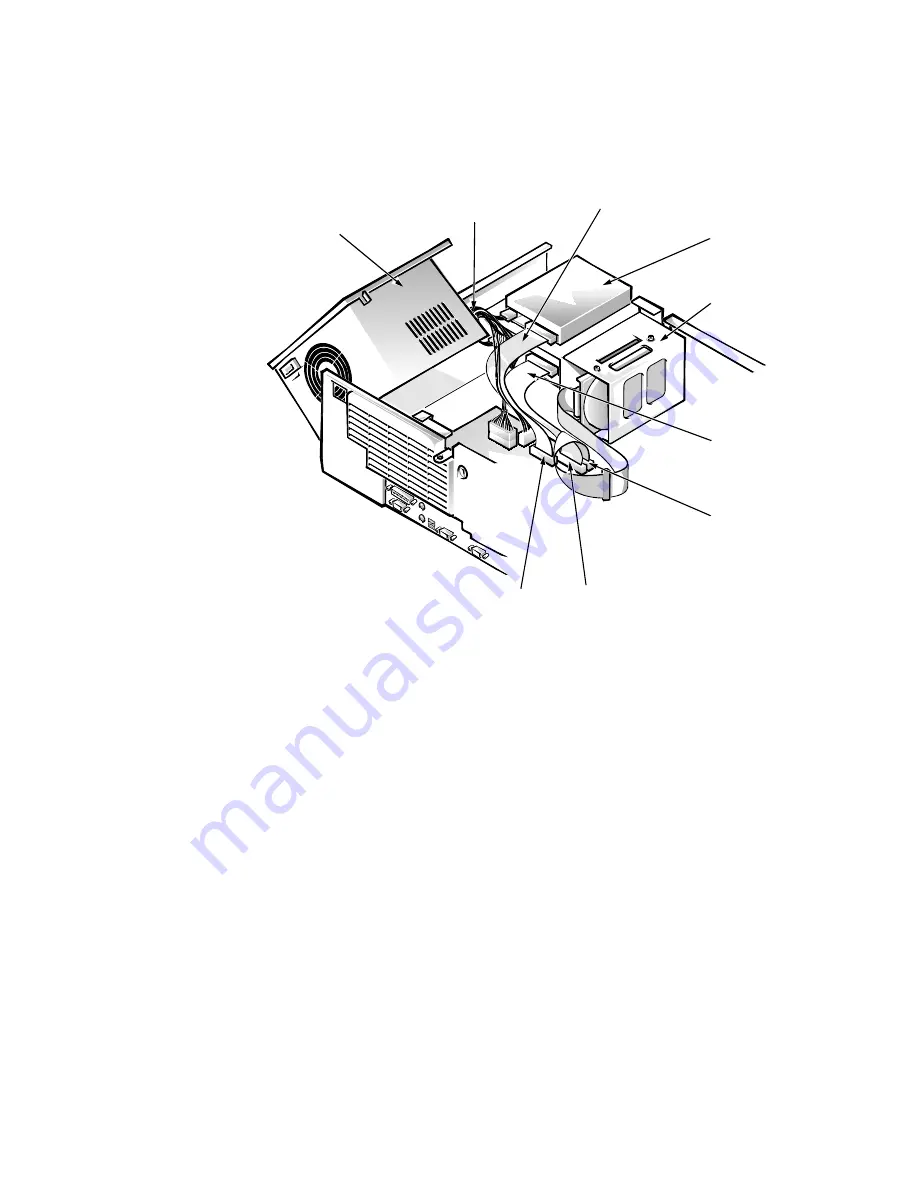
Figure 5-7 shows an example of drive hardware that can be installed in the
computer. Refer to this figure when you perform any of the procedures in the
following subsections.
)LJXUH'ULYH+DUGZDUH
([WHUQDOO\$FFHVVLEOH'ULYH$VVHPEOLHV
The following subsections contain removal/replacement procedures for drives
installed in the externally accessible drive bays.
diskette/tape drive
interface cable
DC power
cable
DSKT connector
system
power
supply
hard-disk drive bracket
secondary EIDE interface
connector (IDE2)
primary EIDE interface
connector (IDE1)
EIDE cable
3.5-inch diskette
drive
Summary of Contents for OptiPlex G1
Page 1: ...ZZZ GHOO FRP HOO 2SWL3OH 0DQDJHG 3 6 VWHPV 6 59 0 18 ...
Page 44: ...1 34 Dell OptiPlex G1 Managed PC Systems Service Manual ...
Page 58: ...3 8 Dell OptiPlex G1 Managed PC Systems Service Manual ...
Page 82: ...4 24 Dell OptiPlex G1 Managed PC Systems Service Manual ...
Page 132: ...6 26 Dell OptiPlex G1 Managed PC Systems Service Manual ...
Page 143: ......


