System Overview
1-23
)LJXUH'&3RZHU&RQQHFWRUV3/RZ3URILOH&KDVVLVDQG3
$OO2SWL3OH[*&KDVVLV
'&3RZHU'LVWULEXWLRQ
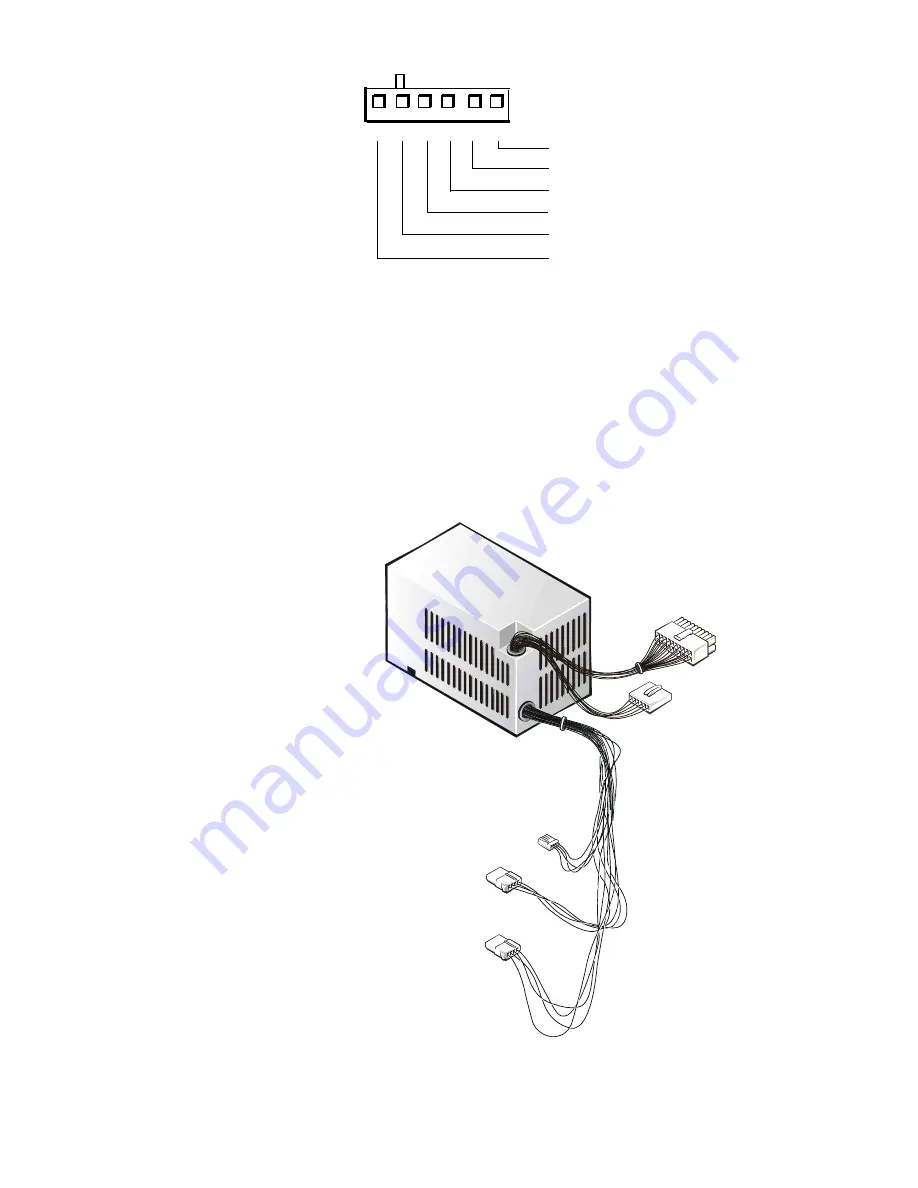
Figures 1-18 through 1-20 provide the following information about DC power
distribution:
Power-supply connector identification
Power cable connections for diskette, tape, CD-ROM, and hard-disk drives
Power distribution to sockets and connectors on the system board
)LJXUH'&3RZHU&DEOHVIRUWKH/RZ3URILOH&RPSXWHU
1
2
3
4
+3.3 VDC (blue/white)
common (black)
common (black)
5
P2, P7
6
+3.3 VDC (blue/white)
+3.3 VDC (blue/white)
common (black)
P5
P4
P3
P2
P1
Summary of Contents for OptiPlex G1
Page 1: ...ZZZ GHOO FRP HOO 2SWL3OH 0DQDJHG 3 6 VWHPV 6 59 0 18 ...
Page 44: ...1 34 Dell OptiPlex G1 Managed PC Systems Service Manual ...
Page 58: ...3 8 Dell OptiPlex G1 Managed PC Systems Service Manual ...
Page 82: ...4 24 Dell OptiPlex G1 Managed PC Systems Service Manual ...
Page 132: ...6 26 Dell OptiPlex G1 Managed PC Systems Service Manual ...
Page 143: ......


