background image

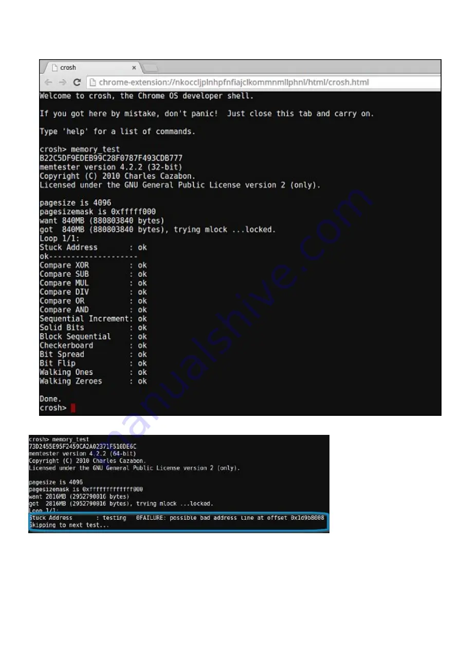
5. A diagnostic screen displays the result of the memory test passed without any errors.

Example of a memory test failure.

Checking network status

If you are having trouble connecting to the Internet, use the steps in one or more of the following sections to test the network adapter:

Follow the instruction to gather the information about the network and diagnose the network errors.

74

Troubleshooting

Summary of Contents for Latitude 7410

Page 1: ...Dell Latitude 7410 Chromebook Enterprise Service Manual 1 Regulatory Model P119G P131G Regulatory Type P119G002 P131G002 August 2020 Rev A00 ...

Page 2: ...ential damage to hardware or loss of data and tells you how to avoid the problem WARNING A WARNING indicates a potential for property damage personal injury or death 2020 Dell Inc or its subsidiaries All rights reserved Dell EMC and other trademarks are trademarks of Dell Inc or its subsidiaries Other trademarks may be trademarks of their respective owners ...

Page 3: ...ential damage to hardware or loss of data and tells you how to avoid the problem WARNING A WARNING indicates a potential for property damage personal injury or death 2020 Dell Inc or its subsidiaries All rights reserved Dell EMC and other trademarks are trademarks of Dell Inc or its subsidiaries Other trademarks may be trademarks of their respective owners ...

Page 4: ...over 22 Removing the base cover 22 Installing the base cover 25 Battery 26 Lithium ion battery precautions 26 Disconnecting the battery cable 27 Reconnecting the battery cable 27 Removing the battery 28 Installing the battery 29 Solid state drive 30 Removing the 2230 Solid State Drive 30 Installing the 2230 Solid State Drive 31 Removing the 2280 Solid State Drive 32 Installing the 2280 Solid State...

Page 5: ...yboard 51 Installing the keyboard 53 Palmrest assembly 54 Removing and Installing the Palmrest assembly 54 Chapter 5 Troubleshooting 56 SupportAssist Onboard Diagnostics 56 Launching SupportAssist 56 Basic troubleshooting 58 Power issues 58 CROSH 62 CROSH commands 63 Chrome commands 65 Commonly used CROSH command 70 Check battery charging status 70 Reset Chromebook 77 Recovery Chromebook 78 Recove...

Page 6: ...s not authorized by Dell is not covered by your warranty See the safety instructions that is shipped with the product or at www dell com regulatory_compliance CAUTION Before touching anything inside your computer ground yourself by touching an unpainted metal surface such as the metal at the back of the computer While you work periodically touch an unpainted metal surface to dissipate static elect...

Page 7: ...no longer allowed they do not provide adequate protection Touching the chassis before handling parts does not ensure adequate ESD protection on parts with increased sensitivity to ESD damage Handle all static sensitive components in a static safe area If possible use anti static floor pads and workbench pads When unpacking a static sensitive component from its shipping carton do not remove the com...

Page 8: ...packaging that the new part arrived in The ESD bag should be folded over and taped shut and all the same foam packing material should be used in the original box that the new part arrived in ESD sensitive devices should be removed from packaging only at an ESD protected work surface and parts should never be placed on top of the ESD bag because only the inside of the bag is shielded Always place p...

Page 9: ...e a selection press the Pen tip on the display screen Clicking Tap the display screen once with the Pen tip or touch the Pen to the screen with enough pressure to register a click Dragging Select an object then slide the Pen tip across the screen to move the object Erasing Press and hold the bottom barrel button and move the tip over the area you want to erase Context Menu Right click Press and ho...

Page 10: ...ts Keys Primary behavior Secondary behavior Fn Key Esc behavior Esc behavior Browser Back F1 behavior Reload current page F2 behavior Open your page in fullscreen mode F3 behavior Switch to your next tab or window F4 behavior Decrease screen brightness F5 behavior Increase screen brightness F6 behavior Mute F7 behavior Decrease the volume F8 behavior Increase the volume F9 behavior 10 Technology a...

Page 11: ...ortcut keys Shortcut keys Shortcut Function Esc Stop the loading of your current page Ctrl F5 Decrease keyboard brightness Ctrl F6 Increase keyboard brightness Alt Up arrow Page up Alt Down arrow Page down Alt Left arrow Backspace Go to previous page in your browsing history Alt Right arrow Shift Backspace Go to the next page in your browsing history Ctrl Right arrow Move to the end of the next wo...

Page 12: ...the DOM Inspector Ctrl Shift L Locks the screen Ctrl Shift N Open a new window in incognito mode Ctrl Shift B Toggle the bookmark bar Ctrl Shift Q Sign out Google Account Ctrl Shift Q twice Sign out Google Account on Chrome OS Ctrl Shift R Reload your current page without using cached content Ctrl Shift T Reopen the last tab being closed Google Chrome remembers the last 10 tabs being closed Ctrl S...

Page 13: ... Shift Tab Go to the previous tab in the window Ctrl Shift Refresh Rotate screen 90 degrees Ctrl Shift Reset screen scale Ctrl Shift Increase screen scale Ctrl Shift Decrease screen scale Ctrl Shift Refresh Rotate screen 90 degrees Ctrl Zoom in on the page Ctrl Zoom out on the page Alt click a link Open the link you clicked in a new background tab Alt 1 through Alt 8 Go to the window at the specif...

Page 14: ...F and displays the user mode If the system does not support privacy mode the function will be as per the operating system or application specific F12 default behavior Operating system or application specific F12 default behavior Project mode Toggles between mirrored and extended display modes Null Delete Delete function Null Power Button Changes the system power state Null Language Key Switches be...

Page 15: ...n doesn t necessarily mean they do USB Type C and USB 3 1 USB 3 1 is a new USB standard USB 3 s theoretical bandwidth is 5 Gbps while USB 3 1 s is 10 Gbps That s double the bandwidth as fast as a first generation Thunderbolt connector USB Type C isn t the same thing as USB 3 1 USB Type C is just a connector shape and the underlying technology could just be USB 2 or USB 3 0 In fact Nokia s N1 Andro...

Page 16: ...be fast enough Furthermore no USB 2 0 connection could ever come close to the 480Mbps theoretical maximum throughput making data transfer at around 320 Mbps 40 MB s the actual real world maximum Similarly USB 3 2 Gen 1 connections will never achieve 4 8Gbps We will likely see a real world maximum rate of 400 MB s with overheads At this speed USB 3 2 Gen 1 is a 10x improvement over USB 2 0 Applicat...

Page 17: ...es to take advantage of the higher speed capability of the new protocol the connector itself remains the same rectangular shape with the four USB 2 0 contacts in the exact same location as before Five new connections to carry receive and transmitted data independently are present on USB 3 2 Gen 1 cables and only come into contact when connected to a proper Super Speed USB connection Technology and...

Page 18: ...n the system Topics Major components of your system Major components of your system 1 Base cover 2 Battery 3 Solid State Drive Thermal plate 4 Solid State Drive 5 Speakers 6 Keyboard 7 Palmrest 8 Display Assembly 9 Power Button Module 10 System Board 3 18 Major components of your system ...

Page 19: ...11 WWAN Card 12 Fan Assembly 13 Palmrest Antenna Assembly Major components of your system 19 ...

Page 20: ...e drive WWAN card Palmrest antenna Heatsink assembly Display assembly Speakers Power button System board Keyboard Palmrest assembly MicroSD card Removing the microSD card Prerequisites 1 Follow the procedure in Before working inside your computer 4 20 Disassembly and reassembly ...

Page 21: ...About this task Steps 1 Push the microSD card to release it from the computer 2 Slide the microSD card out of the computer Disassembly and reassembly 21 ...

Page 22: ...into place Next steps Follow the procedures in After working inside your computer Base cover Removing the base cover Prerequisites 1 Follow the procedure in Before working inside your computer About this task The following images indicate the location of the base cover and provide a visual representation of the removal procedure 22 Disassembly and reassembly ...

Page 23: ...Disassembly and reassembly 23 ...

Page 24: ...e top left corner use a plastic scribe to pry the base cover outwards to release the base cover from the palm rest assembly and remove it from the system NOTE Do not slide the scribe through the edge of the top side of the base cover as it damages the latches inside the base cover 24 Disassembly and reassembly ...

Page 25: ...g a component remove the existing component before performing the installation procedure About this task The following images indicate the location of the base cover and provide a visual representation of the installation procedure Disassembly and reassembly 25 ...

Page 26: ...ion when handling Lithium ion batteries Discharge the battery completely before removing it Disconnect the AC power adapter from the system and operate the computer solely on battery power the battery is fully discharged when the computer no longer turns on when the power button is pressed Do not crush drop mutilate or penetrate the battery with foreign objects Do not expose the battery to high te...

Page 27: ...ll com or authorized Dell partners and resellers Disconnecting the battery cable Prerequisites 1 Follow the procedure in Before working inside your computer 2 Remove the base cover About this task The following images indicate the location of the battery cable and provide a visual representation of the disconnection procedure Steps Using the pull tab remove the battery cable from connector the sys...

Page 28: ...procedure in After working inside your computer Removing the battery Prerequisites 1 Follow the procedure in Before working inside your computer 2 Remove the base cover 3 Disconnect the battery cable About this task The following images indicate the location of the battery and provide a visual representation of the removal procedure 28 Disassembly and reassembly ...

Page 29: ...the system Installing the battery Prerequisites If you are replacing a component remove the existing component before performing the installation procedure About this task The following images indicate the location of the battery and provide a visual representation of the installation procedure Disassembly and reassembly 29 ...

Page 30: ...l the base cover 3 Follow the procedure in After working inside your computer Solid state drive Removing the 2230 Solid State Drive Prerequisites 1 Follow the procedure in Before working inside your computer 2 Remove the base cover 3 Disconnect the battery cable About this task The following images indicate the location of the SSD solid state drive and provide a visual representation of the remova...

Page 31: ...be removed with the SSD since the adhesive is strong and to avoid any damage to the SSD 3 Remove the SSD from the SSD bracket Installing the 2230 Solid State Drive Prerequisites If you are replacing a component remove the existing component before performing the installation procedure About this task The following images indicate the location of the SSD solid state drive and provides a visual repr...

Page 32: ...e M2x2 screw securing it to the system board Next steps If you are replacing a component remove the existing component before performing the installation procedure 1 Reconnect the battery cable 2 Install the base cover 3 Follow the procedure in After working inside your computer Removing the 2280 Solid State Drive Prerequisites 1 Follow the procedure in Before working inside your computer 2 Remove...

Page 33: ... the system board 2 Remove the thermal plate from over the SSD NOTE The thermal plate should be removed with the SSD since the adhesive is strong and to avoid any damage to the SSD Installing the 2280 Solid State Drive Prerequisites If you are replacing a component remove the existing component before performing the installation procedure About this task The following images indicate the location ...

Page 34: ...ystem board and replace the single M2x2 screw securing it to the system board Next steps If you are replacing a component remove the existing component before performing the installation procedure 1 Reconnect the battery cable 2 Install the base cover 3 Follow the procedure in After working inside your computer WWAN card Removing the WWAN card Prerequisites 1 Follow the procedure in Before working...

Page 35: ... remove the WWAN bracket from over the WWAN card 3 Disconnect the antenna cables from the WWAN card 4 Lift and remove the WWAN card from its slot on the system board Installing the WWAN card Prerequisites If you are replacing a component remove the existing component before performing the installation procedure About this task The following images indicate the location of the WWAN card and provide...

Page 36: ... Replace the WWAN bracket on top of the antenna cables 4 Replace the single M2x3 screw securing it to the system board Next steps 1 Reconnect the battery cable 2 Install the base cover 3 Follow the procedure in After working inside your computer Palmrest antenna Disconnecting the WLAN antenna Prerequisites 1 Follow the procedure in Before working inside your computer 2 Remove the base cover 36 Dis...

Page 37: ...soldered onto the system board it cannot be removed In case of WLAN failure the system board needs to be replaced Heatsink assembly Removing the heatsink assembly Prerequisites 1 Follow the procedure in Before working inside your computer 2 Remove the base cover 3 Disconnect the battery cable About this task The following images indicate the location of the heatsink assembly and provide a visual r...

Page 38: ... board 3 Remove the five M2x2 5 screw from the heatsink assembly then lift and remove the heatsink assembly from the system board Installing the heatsink assembly Prerequisites If you are replacing a component remove the existing component before performing the installation procedure About this task The following images indicate the location of the heatsink assembly and provide a visual representa...

Page 39: ...as and replace the single M2x2 5 screw that secures the shield plate to te system board NOTE The fan cable must be routed under the shield plate Next steps 1 Reconnect the battery cable 2 Install the base cover 3 Follow the procedure in After working inside your computer Display assembly Removing the display assembly Prerequisites 1 Follow the procedure in Before working inside your computer 2 Rem...

Page 40: ... Disconnect the battery cable About this task The following images indicate the location of the display assembly and provide a visual representation of the removal procedure 40 Disassembly and reassembly ...

Page 41: ...om the connectors on the system board CAUTION Pull the pull tab vertically to disconnect the display cable from the system board 5 Remove the two M2 5x5 screws from the left hinge and fold it back 6 Remove the two M2 5x5 screws from the right hinge and fold it back 7 Lift and remove the display assembly from the chassis Installing the display assembly Prerequisites If you are replacing a component...

Page 42: ...42 Disassembly and reassembly ...

Page 43: ...he two M2x2 screws 6 Route the WWAN antenna cables though the routing points provided and connect them to the WWAN card 7 Place the WWAN bracket on to the antennas and install the single M2x2 5 screw Next steps 1 Reconnect the battery cable 2 Install the base cover 3 Follow the procedure in After working inside your computer Speakers Removing the speaker Prerequisites 1 Follow the procedure in Bef...

Page 44: ... the installation procedure About this task The following images indicate the location of the speaker and provide a visual representation of the installation procedure Steps 1 Align and replace the right speaker into its slot in the palmrest assembly and route the speaker cable along the guide path 2 Connect the speaker cable to its connector on the system board Next steps 1 Install the battery 2 ...

Page 45: ...NOTE System board can be disassembled without having to remove the heatsink assembly About this task The following images indicate the location of the power button and provide a visual representation of the removal procedure Steps 1 Remove the two M2x2 5 screws securing the power button to the palmrest assembly 2 Remove the power button from its slot in the palmrest assembly Disassembly and reasse...

Page 46: ... button and provide a visual representation of the installation procedure Steps 1 Replace the power button into its slot in the palmrest assembly 2 Replace the two M2x2 5 screws securing power button to the palmrest assembly Next steps 1 Install the a System board b Heatsink c WLAN antenna d WWAN card e SSD f Battery g Base cover 2 Follow the procedure in After working inside your computer 46 Disa...

Page 47: ... Base cover b Battery c Solid state drive d WLAN antenna e Heatsink assembly NOTE System board can be disassembled without having to remove the heatsink assembly About this task The following images indicate the location of the system board and provide a visual representation of the removal procedure Disassembly and reassembly 47 ...

Page 48: ...48 Disassembly and reassembly ...

Page 49: ...ble Touchpad cable 5 Remove the two M2x5 screws securing the Type C USB bracket to the system board 6 Remove the USB Type C bracket from the system board 7 Remove the three M2x2 5 screw securing the system board to the palmrest assembly 8 Remove the system board from the system Installing the system board Prerequisites If you are replacing a component remove the existing component before performin...

Page 50: ...50 Disassembly and reassembly ...

Page 51: ...tennas 9 Place the WWAN bracket on the antennas and install the single M2x2 5 screws securing it to the system board Next steps If you are replacing a component remove the existing component before performing the installation procedure 1 Install the a Heatsink assembly b WLAN antennae c Solid state drive d Battery e Base cover 2 Follow the procedure in After working inside your computer Keyboard R...

Page 52: ...ght cable from the touchpad module NOTE For models shipped with a carbon fiber palm rest there are nineteen M1 6x2 screws that secure the keyboard plate to the system NOTE For models shipped with an aluminum palm rest there are twenty six M1 6x2 screws that secure the keyboard plate to the system 52 Disassembly and reassembly ...

Page 53: ...u are replacing a component remove the existing component before performing the installation procedure NOTE When re assembling the keyboard properly seat the keyboard using the positioning pins on the keyboard support plate T he screw holes can be identified by the black mylar covering it on the other side Disassembly and reassembly 53 ...

Page 54: ...mbly Next steps If you are replacing a component remove the existing component before performing the installation procedure 1 Install the a System board b Heatsink assembly c Solid state drive d Battery e Base cover 2 Follow the procedure in After working inside your computer Palmrest assembly Removing and Installing the Palmrest assembly Prerequisites 1 Follow the procedure in Before working insi...

Page 55: ...esentation of the removal procedure Steps Once all the underlying components are removed you are left with the palmrest assembly Next steps If you are replacing a component remove the existing component before performing the installation procedure 1 Install the a Keyboard b System board c Power button d Speakers e Display assembly f Heatsink assembly g WWAN card h Solid state drive i Battery j Bas...

Page 56: ...ve mode 2 Repeat tests 3 Display or save test results 4 Run thorough tests to introduce additional test options to provide extra information about the failed device s 5 View status messages that inform you if tests are completed successfully 6 View error messages that inform you of problems encountered during testing Launching SupportAssist This section outlines how to launch SupportAssist on Lati...

Page 57: ...aunch system scan quick test automatically If you need to test specific components press Esc to abort the system scan 2 Click the arrow icon to proceed to the Advanced page to test selected components 3 Select and test specific components from the Advanced page Troubleshooting 57 ...

Page 58: ...device is causing the problem You are done b If the Chromebook still does not start or exhibits the same problem do not reconnect anything and continue troubleshooting 2 The battery life might be too low Plug the Chromebook into the AC adapter and let it charge for at least an hour and try turning it on again NOTE When a new Chromebook is used for the first time the battery is still in shipping mo...

Page 59: ...evice is not muted Try adjusting the volume 2 Try rebooting the Chromebook 3 Try playing audio from various sources including YouTube and audio files stored locally on the Chromebook If the speakers are not responding when attempting to listen to audio 1 Unplug the device from all cables USB headphones and displays 2 Try playing audio from various sources including YouTube and audio files stored l...

Page 60: ...otkeys issues Issue Possible solutions Touchpad not responding If the touch pad has stopped responding try the following steps to resolve the issue Try moving the cursor after each step 1 Tap the Esc key several times 2 Drumroll the fingers across the touch pad for a few seconds 3 Restart the Chrome OS by holding down the power button until the device turns off and then turn it back on again 4 If ...

Page 61: ...pear try closing inactive tabs or other programs to free up more memory 2 If issue persists please see He s Dead Jim from Google knowledge base Chrome OS is missing or damaged If the Chromebook does not start and displays the message Chrome OS is missing or damaged Please insert a recovery USB stick into the USB ports on the device Perform a system recovery See performing Recover Chromebook for mo...

Page 62: ...one inside the OS Chrome Shell CROSH and the Chrome URL commands provide some troubleshooting tools information and advanced settings CROSH is a command line interface similar to the Linux BASH or Windows command cmd exe terminals Chrome OS is based on Linux but CROSH does not recognize most Linux commands The most useful commands for troubleshooting are memory test storage_test_1 storage_test_2 p...

Page 63: ...ument defaults to a 300 s test bt_console agent capability Enters a Bluetooth debugging console The Optional argument specifies the capability of a pairing agent the console provides see the Bluetooth Core specification for valid options chaps_debug start stop log_level Sets the chaps debug logging level No arguments will start verbose logging connectivity Shows connectivity status experimental_st...

Page 64: ...sed to play record audio samples and enable beam forming on Pixel sound beamforming on off will enable disable the feature sound record duration will start recording sound play filename plays the recorded audio samples storage_status Reads storage device SMART health status vendor attributes and error logs storage_test_1 Performs a short offline SMART test storage_test_2 Performs an extensive read...

Page 65: ...hat Dell supports Memory Troubleshooting chrome memory View running processes and memory utilization Module Load chrome conflicts Shows conflicts of all modules loaded by Chrome Chrome Sync Status chrome syncchrome sync internals Allows troubleshooting of connected accounts Connectivity Troubleshooting chrome net internals Comprehensive network connectivity diagnostics including DNS analysis Water...

Page 66: ...his page since these are experimental these might not work as expected and might cause issues Enable these features and use it at your own risk 2 chrome dns This displays the list of host names for which the browser will pre fetch the DNS records 3 chrome downloads This is also available from the Menu Downloads Shortcut key is Ctrl J 66 Troubleshooting ...

Page 67: ...om the Menu Tools Extensions 5 chrome bookmarks This is also available from the Menu Bookmarks Bookmark Manager Short cut key is Ctrl Shift O 6 chrome history This is also available from the Menu History Short cut key is Ctrl H Troubleshooting 67 ...

Page 68: ...to save netlogs and the external Catapult netlog_viewer to view them chrome net internals This displays all networking related information Use this to capture network events generated by the browser You can also export this data You can view DNS host resolver cache One of the important features in this feature is Test If a URL failed to load you can go to chrome net internals click on Tests tab ty...

Page 69: ...sions This displays the number of sessions and magic list that are currently running 11 chrome settings This is also available from the Menu Options on Windows and Menu Preferences on Linux From here you can control various browser related settings 12 chrome sync internals This gives information about the Chrome sync feature including the Sync URL used by Google and sync statistics Troubleshooting...

Page 70: ...re not supported on the eMMC storage device Check battery charging status The Chrome Shell CROSH includes a simple battery health diagnostic test This is to confirm that the battery is charging and to check on the battery health and discharge rate Follow the instruction provided to check on the battery charging status 1 Connect the AC adapter to the Chromebook and a power outlet 2 Turn on and sign...

Page 71: ...nfirm that the battery is charging Check battery health Follow the steps to evaluate the health of the Chromebook battery and check the discharge rate 1 Disconnect the AC adapter from the Chromebook 2 Turn on and sign in to Chromebook 3 Open the Chrome browser Troubleshooting 71 ...

Page 72: ...ry health percentage is greater than 50 the battery is within the expected wear limits If the Battery health percentage is equal to or less than 50 and the battery is less than a year old the battery is outside expected wear limits and might need to be replaced If the test results show that Battery is Unknown the battery might need to be replaced 72 Troubleshooting ...

Page 73: ... NOTE This will approximately take 20 minutes to complete the test and it also depends on the capacity of the memory 1 Turn on and sign in to Chromebook 2 Open the Chrome browser 3 Press CTRL ALT T to open CROSH 4 Type memory_test into CROSH and then press Enter Troubleshooting 73 ...

Page 74: ...a memory test failure Checking network status If you are having trouble connecting to the Internet use the steps in one or more of the following sections to test the network adapter Follow the instruction to gather the information about the network and diagnose the network errors 74 Troubleshooting ...

Page 75: ...1 Turn on and sign in to Chromebook 2 Open the Chrome browser 3 Press CTRL ALT T to open CROSH 4 Type network_diag into CROSH and then press Enter Troubleshooting 75 ...

Page 76: ...SH performs a set of network diagnostic tests A diagnostic screen displays the results of the network adapter health test 6 The diagnostic test log is saved as a txt plain text file in the Files app 76 Troubleshooting ...

Page 77: ...ccounts NOTE Do not follow the instructions below if you re using a managed Chrome device as you will not be able to re enroll your device after powerwashing it Follow these steps to reset your Chromebook to its original factory state 1 Click the status area in the lower right corner where your account picture appears 2 Click Settings icon represented by the gear symbol 3 Click Show advanced setti...

Page 78: ...f message refer to Chrome OS verification is turned off section below Step 2 Create the recovery USB flash drive or SD card Insert a USB flash drive or SD card into your computer and follow the instructions below Table 16 USB flash drive or SD card Operating System Instructions Chrome Device Instructions Create a recovery flash drive by using the Image Burner The tool may not be available in all l...

Page 79: ... Because the data stored on your Chromebook has been cleared you will need to go through the initial setup again Make sure you sign in with your primary Google Account because this account will be set as the owner account Chrome OS verification is turned off Message By default Chromebooks are set to the normal user mode If you ve set the user mode to developer mode instead you ll see a screen with...

Page 80: ...Windows After you have completed recovery you need to format your USB or SD card using the recovery tool You successfully recovered your Chromebook but now Windows does not recognize the whole size of the USB or SD card used for recover After you have completed recovery you need to format your USB or SD card using the recovery tool 80 Troubleshooting ...

Page 81: ... and telephone based support and service options Availability varies by country and product and some services may not be available in your area To contact Dell for sales technical support or customer service issues Steps 1 Go to Dell com support 2 Select your support category 3 Verify your country or region in the Choose a Country Region drop down list at the bottom of the page 4 Select the approp...

Reviews: