background image


2.

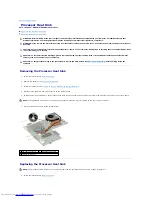
Place the processor heat sink on the system board.  


3.

Align the four captive screws on the processor heat sink with the screw holes on the system board and tighten the screws in sequential order (indicated 
on the processor heat sink).  


4.

Connect the fan cable to the connector on the system board.  


5.

Follow the instructions from 

step 5

 to 

step 17

 in 

Replacing the System Board

.  


6.

Replace the battery (see 

Replacing the Battery

).  


Back to Contents Page


NOTE: 

The appearance and number of screws on the processor heat sink may vary based on the your computer model.


CAUTION: 

Before turning on the computer, replace all screws and ensure that no stray screws remain inside the computer. Failure to do so may 

result in damage to the computer.

Summary of Contents for Inspiron M5010

Page 1: ... the United States and or other countries Other trademarks and trade names may be used in this document to refer to either the entities claiming the marks and names or their products Dell Inc disclaims any proprietary interest in trademarks and trade names other than its own Before You Begin Battery Base Cover Memory Module s Optical Drive Keyboard Palm Rest Wireless Mini Card Media Card Reader Bo...

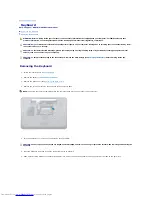
Page 2: ...y see Replacing the Battery WARNING Before working inside your computer read the safety information that shipped with your computer For additional safety best practices information see the Regulatory Compliance Homepage at www dell com regulatory_compliance CAUTION Only a certified service technician should perform repairs on your computer Damage due to servicing that is not authorized by Dell is ...

Page 3: ...Back to Contents Page ...

Page 4: ...Computer Use the following safety guidelines to help protect your computer from potential damage and to help to ensure your own personal safety CAUTION To avoid losing data save and close all open files and exit all open programs before you turn off your computer WARNING Before working inside your computer read the safety information that shipped with your computer For additional safety best pract...

Page 5: ... Disconnect all attached devices from your computer 7 Remove the battery see Removing the Battery 8 Turn the computer top side up open the display and press the power button to ground the system board Back to Contents Page CAUTION To avoid damaging the computer perform the following steps before you begin working inside the computer CAUTION To disconnect a network cable first unplug the cable from...

Page 6: ...duct model number in the Select Your Product Model list d Click Confirm 4 A list of results appear on the screen Click BIOS 5 Click Download Now to download the latest BIOS file The File Download window appears 6 Click Save to save the file on your desktop The file downloads to your desktop 7 Click Close if the Download Complete window appears The file icon appears on your desktop and is titled th...

Page 7: ...e 1 Follow the instructions in Before You Begin 2 Align the connector on the Bluetooth module with the connector on the system board and press the Bluetooth module until it is fully seated 3 Replace the palm rest see Replacing the Palm Rest WARNING Before working inside your computer read the safety information that shipped with your computer For additional safety best practices information see th...

Page 8: ...le s see Replacing the Memory Module s 7 Replace the base cover see Replacing the Base Cover 8 Replace the battery see Replacing the Battery Back to Contents Page CAUTION Before turning on the computer replace all screws and ensure that no stray screws remain inside the computer Failure to do so may result in damage to the computer ...

Page 9: ...ape that secures the camera module to the display cover 12 Remove the camera module from the latches that secure it 13 Lift the camera module off the display cover WARNING Before working inside your computer read the safety information that shipped with your computer For additional safety best practices information see the Regulatory Compliance Homepage at www dell com regulatory_compliance CAUTIO...

Page 10: ...lace the display assembly see Replacing the Display Assembly 7 Replace the palm rest see Replacing the Palm Rest 8 Replace the keyboard see Replacing the Keyboard 9 Replace the optical drive see Replacing the Optical Drive 10 Replace memory module s see Replacing the Memory Module s 11 Replace the base cover see Replacing the Base Cover 12 Replace the battery see Replacing the Battery Back to Cont...

Page 11: ... cable from its routing guide 9 Lift the Media Card Reader board out of the computer base WARNING Before working inside your computer read the safety information that shipped with your computer For additional safety best practices information see the Regulatory Compliance Homepage at www dell com regulatory_compliance CAUTION Only a certified service technician should perform repairs on your compu...

Page 12: ... the system board 5 Replace the palm rest see Replacing the Palm Rest 6 Replace the keyboard see Replacing the Keyboard 7 Replace the optical drive see Replacing the Optical Drive 8 Replace memory module s see Replacing the Memory Module s 9 Replace the base cover see Replacing the Base Cover 10 Replace the battery see Replacing the Battery Back to Contents Page CAUTION Before turning on the compu...

Page 13: ...lacing the Battery Back to Contents Page WARNING Before working inside your computer read the safety information that shipped with your computer For additional safety best practices information see the Regulatory Compliance Homepage at www dell com regulatory_compliance CAUTION Only a certified service technician should perform repairs on your computer Damage due to servicing that is not authorize...

Page 14: ...horized by Dell is not covered by your warranty CAUTION To avoid electrostatic discharge ground yourself by using a wrist grounding strap or by periodically touching an unpainted metal surface such as a connector on your computer CAUTION To help prevent damage to the system board remove the main battery see Removing the Battery before working inside the computer CAUTION To prevent intermittent con...

Page 15: ...at Sink 5 Follow the instructions from step 5 to step 17 in Replacing the System Board 6 Replace the battery see Replacing the Battery Back to Contents Page NOTE If a new processor is installed you will receive a new thermal cooling assembly which will include an affixed thermal pad or you will receive a new thermal pad along with documentation to illustrate proper installation NOTE The pin 1 corn...

Page 16: ... best practices information see the Regulatory Compliance Homepage at www dell com regulatory_compliance WARNING If you remove the processor heat sink from the computer when the heat sink is hot do not touch the metal housing of the processor heat sink CAUTION Only a certified service technician should perform repairs on your computer Damage due to servicing that is not authorized by Dell is not c...

Page 17: ...he connector on the system board 5 Follow the instructions from step 5 to step 17 in Replacing the System Board 6 Replace the battery see Replacing the Battery Back to Contents Page NOTE The appearance and number of screws on the processor heat sink may vary based on the your computer model CAUTION Before turning on the computer replace all screws and ensure that no stray screws remain inside the ...

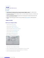
Page 18: ...emove it from the routing guide 11 Remove the four screws two on each side that secure the display assembly to the computer base 12 Lift and remove the display assembly out of the computer base WARNING Before working inside your computer read the safety information that shipped with your computer For additional safety best practices information see the Regulatory Compliance Homepage at www dell co...

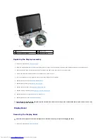
Page 19: ...he Palm Rest 7 Replace the keyboard see Replacing the Keyboard 8 Replace the optical drive see Replacing the Optical Drive 9 Replace memory module s see Replacing the Memory Module s 10 Replace the base cover see Replacing the Base Cover 11 Replace the battery see Replacing the Battery Display Bezel Removing the Display Bezel 1 Follow the instructions in Before You Begin 1 screws 4 2 display cable...

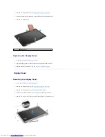
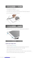
Page 20: ... display panel and gently snap into place 3 Replace the display assembly see Replacing the Display Assembly Display Panel Removing the Display Panel 1 Follow the instructions in Before You Begin 2 Remove the display assembly see Removing the Display Assembly 3 Remove the display bezel see Removing the Display Bezel 4 Disconnect the camera cable from the connector on the camera module 5 Remove the ...

Page 21: ...2 Replace the four screws two on each side that secure the display panel brackets to the display panel 3 Connect the display cable to the display board connector and secure it with the tape 4 Adhere the camera cable to the back of the display panel with the tape 5 Place the display panel on the display cover and connect the camera cable to the connector on the camera module 6 Align the screw holes...

Page 22: ...ay bezel see Replacing the Display Bezel 9 Replace the display assembly see Replacing the Display Assembly Back to Contents Page CAUTION Before turning on the computer replace all screws and ensure that no stray screws remain inside the computer Failure to do so may result in damage to the computer ...

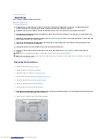
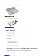
Page 23: ...irs on your computer Damage due to servicing that is not authorized by Dell is not covered by your warranty CAUTION To prevent data loss turn off your computer see Turning Off Your Computer before removing the hard drive Do not remove the hard drive while the computer is On or in Sleep state CAUTION To avoid electrostatic discharge ground yourself by using a wrist grounding strap or by periodicall...

Page 24: ... until it is fully seated 5 Turn the computer over and replace the four screws that secure the hard drive assembly 6 Replace the palm rest see Replacing the Palm Rest 7 Replace the keyboard see Replacing the Keyboard 8 Replace the optical drive see Replacing the Optical Drive 9 Replace memory module s see Replacing the Memory Module s 10 Replace the base cover see Replacing the Base Cover 11 Repla...

Page 25: ...13 Install the drivers and utilities for your computer as needed For more information see the Dell Technology Guide Back to Contents Page ...

Page 26: ... Replacing the System Board 5 Replace the battery see Replacing the Battery WARNING Before working inside your computer read the safety information that shipped with your computer For additional safety best practices information see the Regulatory Compliance Homepage at www dell com regulatory_compliance CAUTION Only a certified service technician should perform repairs on your computer Damage due...

Page 27: ...Back to Contents Page ...

Page 28: ...ion that shipped with your computer For additional safety best practices information see the Regulatory Compliance Homepage at www dell com regulatory_compliance CAUTION Only a certified service technician should perform repairs on your computer Damage due to servicing that is not authorized by Dell is not covered by your warranty CAUTION To avoid electrostatic discharge ground yourself by using a...

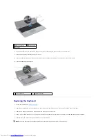
Page 29: ...n 2 Slide the keyboard cable into the connector on the system board and press down on the connector latch to secure the cable 3 Slide the six tabs at the bottom of the keyboard into the slots on the palm rest 4 Gently press around the edges of the keyboard to secure the keyboard under the tabs on the palm rest and slide the keyboard upwards 5 Replace the screw that secures the keyboard to the comp...

Page 30: ...e Cover 7 Replace the battery see Replacing the Battery Back to Contents Page CAUTION Before turning on the computer replace all screws and ensure that no stray screws remain inside the computer Failure to do so may result in damage to the computer ...

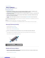
Page 31: ...ide your computer read the safety information that shipped with your computer For additional safety best practices information see the Regulatory Compliance Homepage at www dell com regulatory_compliance CAUTION Only a certified service technician should perform repairs on your computer Damage due to servicing that is not authorized by Dell is not covered by your warranty CAUTION To avoid electros...

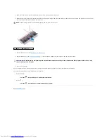
Page 32: ...nd an electrical outlet 6 Turn on the computer As the computer boots it detects the memory module s and automatically updates the system configuration information To confirm the amount of memory installed in the computer Windows Vista Click Start Help and Support Dell System Information Windows 7 Click Start Control Panel System and Security System Back to Contents Page NOTE If the memory module i...

Page 33: ...he two rubber caps that cover the screws 11 Remove the four screws that secure the middle cover to the computer base 12 Release the tabs that secure the middle cover to the computer base WARNING Before working inside your computer read the safety information that shipped with your computer For additional safety best practices information see the Regulatory Compliance Homepage at www dell com regul...

Page 34: ...eplace the Mini Card see Replacing the Mini Card 5 Replace the palm rest see Replacing the Palm Rest 6 Replace the keyboard see Replacing the Keyboard 7 Replace the optical drive see Replacing the Optical Drive 8 Replace memory module s see Replacing the Memory Module s 9 Replace the base cover see Replacing the Base Cover 10 Replace the battery see Replacing the Battery Back to Contents Page 1 ta...

Page 35: ... repairs on your computer Damage due to servicing that is not authorized by Dell is not covered by your warranty CAUTION To avoid electrostatic discharge ground yourself by using a wrist grounding strap or by periodically touching an unpainted metal surface such as a connector on your computer CAUTION To help prevent damage to the system board remove the main battery see Removing the Battery befor...

Page 36: ...em board 5 Connect the appropriate antenna cables to the Mini Card you are installing The following table provides the antenna cable color scheme for the Mini Card supported by your computer 1 antenna cable connectors 2 2 Mini Card 3 screw CAUTION Use firm and even pressure to slide the card into place If you use excessive force you may damage the connector CAUTION The connectors are keyed to ensu...

Page 37: ... see Replacing the Battery 13 Install the drivers and utilities for your computer as required For more information see the Dell Technology Guide Back to Contents Page Auxiliary black triangle black CAUTION Before turning on the computer replace all screws and ensure that no stray screws remain inside the computer Failure to do so may result in damage to the computer NOTE If you are installing a wi...

Page 38: ...ce the screw that secures the optical drive to the computer base 4 Replace the base cover see Replacing the Base Cover WARNING Before working inside your computer read the safety information that shipped with your computer For additional safety best practices information see the Regulatory Compliance Homepage at www dell com regulatory_compliance CAUTION Only a certified service technician should ...

Page 39: ...ry see Replacing the Battery Back to Contents Page CAUTION Before turning on the computer replace all screws and ensure that no stray screws remain inside the computer Failure to do so may result in damage to the computer ...

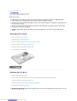
Page 40: ...puter base WARNING Before working inside your computer read the safety information that shipped with your computer For additional safety best practices information see the Regulatory Compliance Homepage at www dell com regulatory_compliance CAUTION Only a certified service technician should perform repairs on your computer Damage due to servicing that is not authorized by Dell is not covered by yo...

Page 41: ... 2 Slide the tabs on the palm rest into the slots on the computer base and gently snap the palm rest into place 3 Replace the five screws that secure the plam rest to the system board 4 Connect the touch pad cable status light cable and power button cable to the connectors on the system board CAUTION To avoid damage to the connectors lift the connector latch and then remove the cables 1 touch pad ...

Page 42: ...place the optical drive see Replacing the Optical Drive 9 Replace the memory module s see Replacing the Memory Module s 10 Replace the base cover see Replacing the Base Cover 11 Replace the battery see Replacing the Battery Back to Contents Page CAUTION Before turning on the computer replace all screws and ensure that no stray screws remain inside the computer Failure to do so may result in damage...

Page 43: ...ition Back to Contents Page WARNING Before working inside your computer read the safety information that shipped with your computer For additional safety best practices information see the Regulatory Compliance Homepage at www dell com regulatory_compliance CAUTION Only a certified service technician should perform repairs on your computer Damage due to servicing that is not authorized by Dell is ...

Page 44: ...System Board 5 Replace the battery see Replacing the Battery WARNING Before working inside your computer read the safety information that shipped with your computer For additional safety best practices information see the Regulatory Compliance Homepage at www dell com regulatory_compliance CAUTION Only a certified service technician should perform repairs on your computer Damage due to servicing t...

Page 45: ...Back to Contents Page ...

Page 46: ...ker cable and Media Card Reader board cable from the connectors on the system board 12 Remove the two screws that secure the system board assembly to the computer base WARNING Before working inside your computer read the safety information that shipped with your computer For additional safety best practices information see the Regulatory Compliance Homepage at www dell com regulatory_compliance CA...

Page 47: ...board assembly to the computer base 9 Connect the display cable VGA connector board cable speaker cable and Media Card Reader board cable to the connectors on the system board 10 Replace the Bluetooth module see Replacing the Bluetooth Module 11 Replace the Mini Card see Replacing the Mini Card 12 Follow the instructions in step 4 and step 5 in Replacing the Hard Drive 13 Replace the palm rest see...

Page 48: ...d in and that the main battery is installed properly 2 Turn on the computer 3 Press F2 during POST to enter the system setup program 4 Navigate to the security tab and enter the service tag in the Set Service Tag field Back to Contents Page ...
Page 49: ...ows Vista start button logo are either trademarks or registered trademarks of Microsoft Corporation in the United States and or other countries Other trademarks and trade names may be used in this document to refer to either the entities claiming the marks and names or their products Dell Inc disclaims any proprietary interest in trademarks and trade names other than its own March 2010 Rev A00 Bac...

Page 50: ...tem board and remove it from the routing guide 11 Remove the VGA connector board from the tab on the computer base 12 Lift the VGA connector board along with the cable off the computer base WARNING Before working inside your computer read the safety information that shipped with your computer For additional safety best practices information see the Regulatory Compliance Homepage at www dell com re...

Page 51: ...e the display assembly see Replacing the Display Assembly 6 Replace the palm rest see Replacing the Palm Rest 7 Replace the keyboard see Replacing the Keyboard 8 Replace the optical drive see Replacing the Optical Drive 9 Replace memory module s see Replacing the Memory Module s 10 Replace the base cover see Replacing the Base Cover 11 Replace the battery see Replacing the Battery Back to Contents...

Reviews: