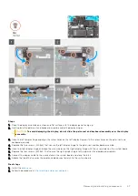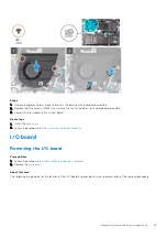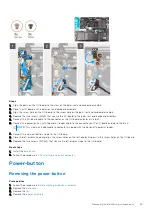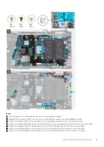
8. Adhere the tape that secures the I/O-board cable to the system board.
9. Close the right display hinge.
10. Replace the four screws (M2.5x4) that secure the right display hinge to the system board and palm-rest and keyboard
assembly.
11. Align the screw holes on the USB Type-C port bracket with the screw holes on the system board.
12. Replace the two screws (M2x4) that secure the USB Type-C port bracket to the system board.
Next steps
1. Install the
.
2. Install the
heat sink without discrete graphics
heat sink with discrete graphics
, whichever applicable.
3. Install the
, whichever applicable.
4. Install the
.
5. Install the
.
6. Install the
, whichever applicable.
7. Install the
.
After working inside your computer
.
Palm-rest and keyboard assembly
Removing the palm-rest and keyboard assembly
Prerequisites
Before working inside your computer
.
2. Remove the
.
3. Remove the
, whichever applicable.
4. Remove the
.
5. Remove the
.
6. Remove the
or
, whichever applicable.
7. Remove the
.
8. Remove the
.
9. Remove the
.
10. Remove the
or
power button with fingerprint reader
.
11. Remove the
.
12. Remove the
NOTE:
The system board can be removed along with the heat sink and memory.
About this task
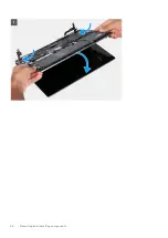
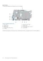
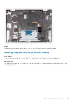
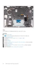
The following image indicates the location of the palm-rest and keyboard assembly and provides a visual representation of the
removal procedure.
54
Removing and installing components

