Service Manual
Reference Information
2-2
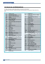
2.2 Acronyms and Abbreviations
The table in the below explains abbreviations used in this service manual.
The contents of this service manual are declared with abbreviations in many parts. Please refer to the
table.
AC
Alternating Current
ADF
Automatic Document Feeder
ASIC
Application Specific Integrated Circuit
ASSY
assembly
BIOS
Basic Input Output System
CCD
Charge Coupled Device
CIS
Contact Image Sensor
CMOS
Complementary Metal Oxide Semiconductor
CN
connector
CON
connector
CPU
Central Processing Unit
dB
decibel
dbA
decibelampere
dBM
decibel milliwatt
DC
direct current
DCU
Diagnostic Control Unit
DPI
Dot Per Inch
DRAM
Dynamic Random Access Memory
DVM
Digital Voltmeter
ECP
Enhanced Capability Port
EEPROM Electronically Erasable Programmable Read
Only Memory
EMI
Electro Magnetic Interference
EP
electrophotographic
EPP
Enhanced Parallel Port
F/W
firmware
GDI
graphics device interface
GND
ground
HBP
Host Based Printing
HDD
Hard Disk Drive
HV
high voltage
HVPS
High Voltage Power Supply
I/F
interface
I/O
Input and Output
IC
integrated circuit
IDE
Intelligent Drive electronics or Imbedded
Drive Electronics
IEEE
Institute of Electrical and Electronics
Engineers. Inc
IPA
Isopropy Alcohol
IPM
Images Per Minutes
LAN
local area network
lb
pound(s)
LBP
Laser Beam Printer
LCD
Liquid Crystal Display
LED
Light Emitting Diode
LSU
Laser Scanning Unit
MB
Megabyte
MHz
Megahertz
NVRAM
Nonvolatile random access memory
OPC
Organic Photo Conductor
PBA
Printed Board Assembly
PCL
Printer Command Language , Printer Control
Language
PDL
Page Discription Language
PPM
Page Per Minute
PTL
Pre-Transfer Lamp
Q’ty
Quantity
RAM
Random Access Memory
ROM
Read Only Memory
SCF
Second Cassette Feeder
SMPS
Switching Mode Power Supply
Spool
Simultaneous Peripheral Operation Online
SW
Switch
Sync
Synchronous or synchronization
USB
Universal Serial Bus
SPGP
S
EC
Printer Graphic Processor
SPL
S
E
C
Printer Language
Summary of Contents for 1815 Mono Laser
Page 1: ...Dell 1815dn Service Manual 27 Mar 2006 ...
Page 28: ...Service Manual System Outline 4 10 ...
Page 126: ...Exploded View Parts List Service Manual 8 3 8 2 Cover Ass y 0 1 2 2 3 2 1 2 2 3 4 5 5 1 5 2 6 ...
Page 127: ...Service Manual Exploded View Parts List 8 4 8 3 Middle Cover Ass y 0 1 2 3 4 5 6 6 ...
Page 129: ...Service Manual Exploded View Parts List 8 6 8 5 Rear Cover Ass y 0 1 2 3 7 4 5 6 8 ...
Page 131: ...Service Manual Exploded View Parts List 8 8 8 7 Fuser Drive Ass y 0 1 2 3 5 5 6 7 8 9 4 ...
Page 132: ...Exploded View Parts List Service Manual 8 9 8 8 Main Drive Ass y 0 2 4 1 3 5 6 8 7 6 7 3 ...
Page 136: ...Exploded View Parts List Service Manual 8 13 8 12 OPE Unit 0 1 2 3 4 5 6 7 8 ...
Page 149: ...Block Diagram Service Manual 9 1 9 9 9 Block Diagram ...
Page 150: ...Connection Diagram Service Manual 10 1 10 10 10 Connection Diagram ...


