Alignment & Adjustments
Service Manual
6-5
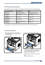
6.2.2 Clearing Jams in the Paper Paths
When a paper jam occurs, Paper Jam appears on the display . Refer to the table below to locate and clear the paper jam.
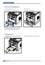
6.2.3 Paper Feed Jam (tray 1)
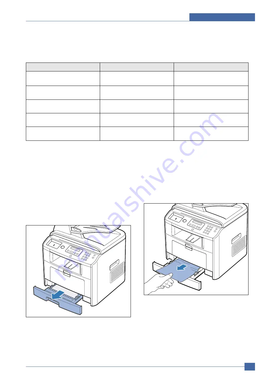
To avoid tearing the paper, pull the jammed paper out gently and slowly. Follow the steps below to clear the jam.
1. Open and close the front cover. The jammed paper
automatically exits the printer. If the paper does not
exit, go to the next step.
2. Pull the paper tray open.
3. Remove the paper by gently pulling it straight out.
If you cannot see the paper or the paper does not
move when pulled, check the fuser area. For more
information, see "Fuser Area Jam".
4. Insert the paper tray into the printer until it snaps into
place.
Printing automatically resumes.
Paper Jam 0
Paper Feed Jam (tray 1)
"Paper Feed Jam (tray 1)" or
Open Front Door
Paper Feed Jam (optional tray 2)
"Paper Feed Jam (optional tray 2)".
Paper Jam 1
Fuser Area Jam
"Fuser Area Jam".
Cartridge Area
Paper Jam 2
Paper Exit Jam
"Paper Exit Jam".
Open Rear Door
Duplex Jam 0
in the duplex unit
"Duplex Jam 0".
Check Inside a
Duplex Jam 1
between the duplex unit and
"Duplex Jam 1".
Check Inside a
fuser area
Operator Panel Message
Location of Jam
Go to
Summary of Contents for 1815 Mono Laser
Page 1: ...Dell 1815dn Service Manual 27 Mar 2006 ...
Page 28: ...Service Manual System Outline 4 10 ...
Page 126: ...Exploded View Parts List Service Manual 8 3 8 2 Cover Ass y 0 1 2 2 3 2 1 2 2 3 4 5 5 1 5 2 6 ...
Page 127: ...Service Manual Exploded View Parts List 8 4 8 3 Middle Cover Ass y 0 1 2 3 4 5 6 6 ...
Page 129: ...Service Manual Exploded View Parts List 8 6 8 5 Rear Cover Ass y 0 1 2 3 7 4 5 6 8 ...
Page 131: ...Service Manual Exploded View Parts List 8 8 8 7 Fuser Drive Ass y 0 1 2 3 5 5 6 7 8 9 4 ...
Page 132: ...Exploded View Parts List Service Manual 8 9 8 8 Main Drive Ass y 0 2 4 1 3 5 6 8 7 6 7 3 ...
Page 136: ...Exploded View Parts List Service Manual 8 13 8 12 OPE Unit 0 1 2 3 4 5 6 7 8 ...
Page 149: ...Block Diagram Service Manual 9 1 9 9 9 Block Diagram ...
Page 150: ...Connection Diagram Service Manual 10 1 10 10 10 Connection Diagram ...


