Service Manual
System Outline
4-16
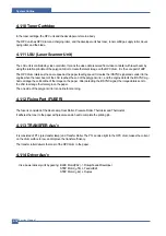
4.1.10 Toner Cartridge
In the toner cartridge, the OPC unit and the developer unit are in a body .
The OPC unit has OPC drum and charging roller, and the developer unit has toner, toner cartridge, supply roller, devel-
oping roller, and the blade.
4.1.11 LSU (Laser Scanner Unit)
The LSU unit is controlled by video controller. It scans the video data received from video controller with laser beam by
using the rotation principle of the polygon mirror to create the latent image on the OPC drum. It is the core part of LBP .
The OPC drum rotates as the same speed as the paper feeding speed. It creates the /HSYNC signal and sends it to the
engine when the laser beam of the LSU reaches the end of the polygon mirror , and the engine detects the /HSYNC sig -
nal to arrange the vertical line of the image on the paper . After detecting the /HSYNC signal, the image data is sent to
the LSU to arrange the its margin on the paper .
The one side of the polygon mirror is one line for scanning.
4.1.12 Fixing Part (FUSER)
The fuser is consisted of the Heat Lamp, Heat Roller , Pressure Roller, Thermistor and Thermostat.
It adheres the toner to the paper with pressure and a heat to complete the printing job.
4.1.13 TRANSFER Ass’y
It is consisted of PTL (pre-transfer lamp) and Transfer Roller. The PTL sends a light to the OPC drum, makes the current
on the drum surface to low, and improve the transfer efficiency.
The transfer roller delivers the toner of the OPC drum to the paper .
4.1.14 Driver Ass’y
It is a power delivery unit by gearing: BLDC Motor(P62) -> Pickup/Feeder/Developer
STEP Motor( 55) -> Feeder/Exit
STEP Motor( 42) -> Duplex
Summary of Contents for 1815 Mono Laser
Page 1: ...Dell 1815dn Service Manual 27 Mar 2006 ...
Page 28: ...Service Manual System Outline 4 10 ...
Page 126: ...Exploded View Parts List Service Manual 8 3 8 2 Cover Ass y 0 1 2 2 3 2 1 2 2 3 4 5 5 1 5 2 6 ...
Page 127: ...Service Manual Exploded View Parts List 8 4 8 3 Middle Cover Ass y 0 1 2 3 4 5 6 6 ...
Page 129: ...Service Manual Exploded View Parts List 8 6 8 5 Rear Cover Ass y 0 1 2 3 7 4 5 6 8 ...
Page 131: ...Service Manual Exploded View Parts List 8 8 8 7 Fuser Drive Ass y 0 1 2 3 5 5 6 7 8 9 4 ...
Page 132: ...Exploded View Parts List Service Manual 8 9 8 8 Main Drive Ass y 0 2 4 1 3 5 6 8 7 6 7 3 ...
Page 136: ...Exploded View Parts List Service Manual 8 13 8 12 OPE Unit 0 1 2 3 4 5 6 7 8 ...
Page 149: ...Block Diagram Service Manual 9 1 9 9 9 Block Diagram ...
Page 150: ...Connection Diagram Service Manual 10 1 10 10 10 Connection Diagram ...

