Precautions
Service Manual
5-23
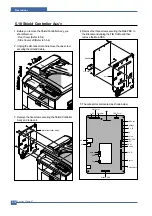
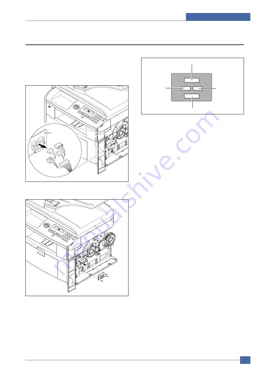
5.14 Connection PCB
1. Before you remove the Connection PCB, you should
remove:
- Rear Cover (Refer to 5.4)
- Side Cover Right (Refer to 5.6.3)
2. Unplug the all connectors.
3. Remove the two screws securing the Connection
PCB and remove it.
4. The connectors are located, as shown below.
Connection
PCB
Connection
PCB
FAN Duplex Exit Motor
Fan Main
HVPS
Duplex
Motor
Summary of Contents for 1815 Mono Laser
Page 1: ...Dell 1815dn Service Manual 27 Mar 2006 ...
Page 28: ...Service Manual System Outline 4 10 ...
Page 126: ...Exploded View Parts List Service Manual 8 3 8 2 Cover Ass y 0 1 2 2 3 2 1 2 2 3 4 5 5 1 5 2 6 ...
Page 127: ...Service Manual Exploded View Parts List 8 4 8 3 Middle Cover Ass y 0 1 2 3 4 5 6 6 ...
Page 129: ...Service Manual Exploded View Parts List 8 6 8 5 Rear Cover Ass y 0 1 2 3 7 4 5 6 8 ...
Page 131: ...Service Manual Exploded View Parts List 8 8 8 7 Fuser Drive Ass y 0 1 2 3 5 5 6 7 8 9 4 ...
Page 132: ...Exploded View Parts List Service Manual 8 9 8 8 Main Drive Ass y 0 2 4 1 3 5 6 8 7 6 7 3 ...
Page 136: ...Exploded View Parts List Service Manual 8 13 8 12 OPE Unit 0 1 2 3 4 5 6 7 8 ...
Page 149: ...Block Diagram Service Manual 9 1 9 9 9 Block Diagram ...
Page 150: ...Connection Diagram Service Manual 10 1 10 10 10 Connection Diagram ...


