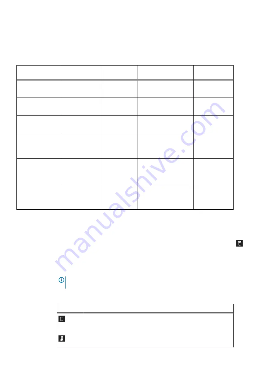
The following table is provided as a reference for the drives that are not hot-swappable in the
X400 capacity cube.
Table 4 Mapping of non-hot-swappable physical slot number to logical slot number for
PowerProtect Data Manager UI alerts
Non-hot-swappable
drive description
Physical slot
number
Logical slot
number
Alert text contains:
Storage controller
attached to drive
Mid panel
X400F:1.92 TB SSD
14
16
Disk 16 in Backplane 1 of
Integrated RAID Controller 1
RAID Controller
Mid panel
X400F:1.92 TB SSDD
15
17
Disk 17 in Backplane 1 of
Integrated RAID Controller 1
RAID Controller
Mid panel
X400F:1.92 TB SSD
16
18
Disk 18 in Backplane 1 of
Integrated RAID Controller 1
RAID Controller
Mid panel
X400H: 3.84 TB SSD
X400F:1.92 TB SSD
17
19
Disk 19 in Backplane 1 of
Integrated RAID Controller 1
RAID Controller
Rear panel
X400H: 12 TB HDD
X400F: 12 TB HDD
12
0
Disk 0 in Backplane 0 of
Storage Controller in Slot 4
HBA330
Rear panel
X400H: 1.92 TB SSD
X400F: 1.92 TB SSD
13
1
Disk 1 in Backplane 0 of
Storage Controller in Slot 4
HBA330
Identifying a faulted drive in the X400 capacity cube
Use the following information to identify a faulted drive:
l
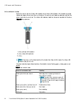
At the front of the X400 capacity cube, check the left control panel Drive indicator
as
described in
l
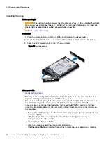
On the drive, check the status indicator as described in
Status LED indicators
Note:
The status LED indicators are always off and only turn on to a solid amber if any error
occurs.
Table 5 Status LED indicators and descriptions
Icon
Description
Condition
Corrective action
Drive indicator The indicator turns
solid amber if there is
a drive error.
Check the System Event Log to
determine if the drive has an error.
Temperature
indicator
The indicator turns
solid amber if the
Ensure that none of the following
conditions exist:
X400 capacity cube CRU procedures
28
PowerProtect X400 Appliance Customer Replaceable Unit (CRU) Procedures


