Customer’s PDU 1
Zone B
AC input
line cord B
Mating connector or
customer-supplied cable
Customer’s PDU 2
Zone A
AC input
line cord A
Mating connector or
customer-supplied cable
Cable connectors are shown
as they exit the bottom rear
of the bay.
Rear view
System bay
P1 P3 P5
P1 P3 P5
P3 and P5 used
depending on
configuration
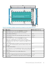
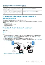
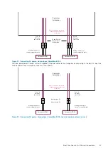
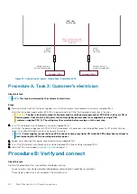
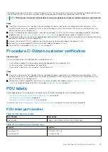
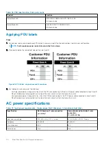
Figure 33. Connecting AC power, single-phase, PowerMax 8000
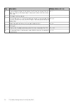
•
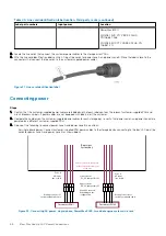
For three-phase power: Connect customer-supplied PDU power cables to the storage bay by connecting to the bay's AC input line
cords for power zone A and power zone B as shown below.
Customer’s PDU 1
Zone B
AC input
line cord B
Mating connector or
customer-supplied cable
Customer’s PDU 2
Zone A
AC input
line cord A
Mating connector or
customer-supplied cable
Cable connectors are shown
as they exit the bottom rear
of the bay.
Rear view
System bay
P1 P2
P1 P2
Lower System: P1
Upper System: P2
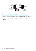
Figure 34. Connecting AC power, three-phase, PowerMax 2000, two dual-engine systems in a rack
Best Practices for AC Power Connections
67


