background image

Use or create no more than one floor tile cutout that is no more than 8 in. (20 cm) wide by 6 in. (15 cm) deep in each 24 x 24 in. (61 x
61 cm) floor tile.

Ensure that the weight of any other objects in the data center does not compromise the structural integrity of the raised floor or the
sub-floor (non-raised floor) of the data center.

Physical space and weight

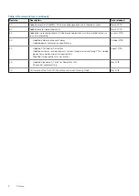
The following table provides the physical space, maximum weights, and clearance for service.

PowerMax 2000

Table 15. Space and weight requirements, PowerMax 2000 

Bay configurations 

a

Height
(in/cm) 

b

Width
(in/cm)

Depth

c

(in/cm)

Weight
(max lbs/kg)

1 system, 1 PowerBrick

75/190

24/61

42/106.7

620/281

1 system, 2 PowerBricks, or

2 systems, 1 PowerBrick each

75/190

24/61

42/106.7

950/430.9

2 systems, 2 PowerBricks in
one system, 1 PowerBrick in
other

75/190

24/61

42/106.7

1280/580

2 systems, 2 PowerBricks
each system

75/190

24/61

42/106.7

1610/730

a.

Clearance for service/airflow is the front at 42 in (106.7 cm) front and the rear at 30 in (76.2 cm).

b.

An additional 18 in (45.7 cm) is recommended for ceiling/top clearance.

c.

Includes rear door.

PowerMax 8000

Table 16. Space and weight requirements, PowerMax 8000  

Bay

configurations 

a

Number of

PowerBricks

Height

b

(in/cm)

Width

c

(in/cm)

Depth

d

(in/cm)

Weight
(max lbs/kg)

System Bay 1

1

75/190

24/61

47/119

805/365

2

75/190

24/61

47/119

1104/501

3

75/190

24/61

47/119

1418/643

4

75/190

24/61

47/119

1667/756

System Bay 2

1

75/190

24/61

47/119

663/301

2

75/190

24/61

47/119

962/436

3

75/190

24/61

47/119

1276/579

4

75/190

24/61

47/119

1525/692

a.

Clearance for service/airflow is the front at 42 in (106.7 cm) front and the rear at 30 in (76.2 cm).

b.

An additional 18 in (45.7 cm) is recommended for ceiling/top clearance.

c.

Measurement includes .25 in. (0.6 cm) gap between bays.

d.

Includes front and rear doors.

22

Physical Weight and Space

Summary of Contents for PowerMax 2000

Page 1: ...Dell EMC PowerMax Family Site Planning Guide PowerMax 2000 and PowerMax 8000 June 2020 Rev 16 0 ...

Page 2: ...tial damage to hardware or loss of data and tells you how to avoid the problem WARNING A WARNING indicates a potential for property damage personal injury or death 2018 2020 Dell Inc or its subsidiaries All rights reserved Dell EMC and other trademarks are trademarks of Dell Inc or its subsidiaries Other trademarks may be trademarks of their respective owners ...

Page 3: ...nd temperature 15 Air volume specifications 15 Temperature altitude and humidity ranges 16 Temperature and humidity range recommendations 16 Air quality requirements 16 Shock and vibration 17 Sound power and sound pressure 17 Hardware acclimation times 17 Optical multimode cables 18 Open systems host and SRDF connectivity 18 Chapter 4 Data Center Safety and Remote Support 20 Fire suppressant discl...

Page 4: ...g requirements 44 Grounding a single bay 44 Chassis to chassis grounding 45 Chapter 10 Dell EMC Racking for PowerMax 2000 46 Two system configurations 46 Two PowerMax 2000 systems 1 PowerBrick 1 PowerBrick configuration 46 Two PowerMax 2000 systems 2 PowerBrick 2 PowerBrick configuration 47 Two PowerMax 2000 systems 2 PowerBrick 1 PowerBrick configuration 48 Two PowerMax 2000 systems 1 PowerBrick ...

Page 5: ...wer Connections 62 Best practices overview for AC power connections 62 Selecting the proper AC power connection procedure 62 Procedure A Working with the customer s electrician onsite 63 Procedure A Task 1 Customer s electrician 63 Procedure A Task 2 Dell EMC Customer Engineer 64 Procedure A Task 3 Customer s electrician 68 Procedure B Verify and connect 68 Procedure C Obtain customer verification...

Page 6: ...m Audience This document is intended for use by customers or company representatives Related documentation Dell EMC PowerMax Family Product Guide Provides information about PowerMax 2000 and 8000 arrays with PowerMaxOS 5978 Dell EMC Best Practices Guide for AC Power Connections for PowerMax 2000 8000 with PowerMaxOS Describes the best practices to assure fault tolerant power to a PowerMax 2000 or ...

Page 7: ...your Dell EMC sales representative for details about obtaining a valid support agreement or to answer any questions about your account Your comments Your suggestions help improve the accuracy organization and overall quality of the documentation Send your comments and feedback to VMAXContentFeedback emc com Revision history Table 2 Revision history Revision Description Date released 16 0 Changed p...

Page 8: ...chassis grounding January 2019 4 0 Updated jumper and line cord tables Updated power consumption specifications October 2018 3 0 Updated PDU label for PowerMax Updated customer rack requirements for rear facing and inward facing PDUs Added power consumption and outlet requirements Modified jumper locations for clarification August 2018 2 0 Updated Procedure A Task 2 for PowerMax 2000 Minor edits a...

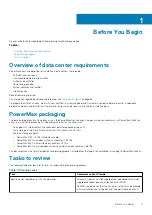
Page 9: ...ystems environments or PowerMax zBrick on arrays in a mainframe environment Depending on the array this consists of An engine with two directors the redundant data storage processing unit Flash storage in two Drive Array Enclosures DAEs each with 24 slots Minimum storage capacity PowerMax 2000 13 TBu Terabytes usable PowerMax 8000 in an open systems environment 53 TBu PowerMax 8000 in a mainframe ...

Page 10: ...rovides details For third party rack support see the detailed physical requirements in Third Party Racking Option for PowerMax 2000 on page 50 and Third Party Racking Option for PowerMax 8000 on page 55 The field representative working the order must Review the requisite information regarding the third party racking option In Sizer select the configuration In the Hardware Options screen under Rack...

Page 11: ... prior to delivery Pre delivery considerations Take into account the following considerations prior to the delivery at your site Weight capacities of the loading dock tailgate and service elevator if delivery is to a floor other than the receiving floor Length and thickness of covering required for floor protection Equipment ramp availability if the receiving floor is not level with computer room ...

Page 12: ...le 4 Shipping and storage environmental requirements continued Condition Setting Storage time unpowered Recommendation Do not exceed 3 consecutive months of unpowered storage 12 Delivery and Transportation ...

Page 13: ... Data Center In addition it may be necessary to contract an environmental consultant to perform the evaluation of RFI field strength and address the mitigation efforts if high levels of RFI are suspected The ambient RFI field strength is inversely proportional to the distance and power level of the emitting device Recommended minimum distance from RF emitting device The following table provides th...

Page 14: ...ccess thermal data through components located within their enclosures Based on ambient temperature and internal activity they set the cooling fan speeds As the inlet temperatures increase the adaptive cooling increases the fan speeds with the resulting platform power increasing up to the maximum values shown below These values along with the SPS recharge power consumption contribute to the maximum...

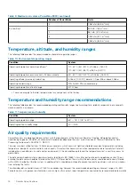
Page 15: ...rature The installation site must meet certain recommended requirements for air volume temperature altitude and humidity ranges and air quality Air volume specifications The following table provides the recommended maximum amount of air volume Table 8 Maximum air volume PowerMax 2000 Number of PowerBricks Units 1 545 cfm 15 3 m3 min 2 1 090 cfm 30 5 m3 min Table 9 Maximum air volume PowerMax 8000 ...

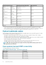
Page 16: ...werMax arrays are designed to be consistent with the requirements of the American Society of Heating Refrigeration and Air Conditioning Engineers ASHRAE Environmental Standard Handbook and the most current revision of Thermal Guidelines for Data Processing Environments ASHRAE TC 9 9 2011 The arrays are best suited for Class 1A Datacom environments which consist of tightly controlled environmental ...

Page 17: ...tical direction NOTE Levels shown apply to all three axes and should be measured with an accelerometer in the equipment enclosures within the cabinet Table 12 Platform shock and vibration Platform condition Response measurement level should not exceed Non operational shock 10 G s 7 ms duration Operational shock 3 G s 11 ms duration Non operational random vibration 40 Grms 5 500Hz 30 minutes Operat...

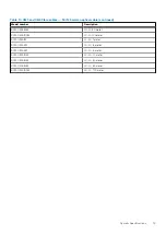
Page 18: ...cal sales representative OM3 cables are used for SRDF connectivity over 4 8 and 16 Gb s Fibre Channel I O modules 10 GbE and 1 GbE I O modules OM4 cables are used for SRDF connectivity over 16 Gb s Fibre Channel I O modules OM4 cables are used with 16 Gb s Fibre Channel I O modules to provide Fibre Channel connection to switches Distances of up to 190 m over 8 Gb s Fibre Channel and 125 m over 16 ...

Page 19: ...mber Description SYM OM3 50M LC LC 50 meter SYM OM3 100M LC LC 100 meter SYM OM4 1M LC LC 1 meter SYM OM4 3M LC LC 3 meter SYM OM4 5M LC LC 5 meter SYM OM4 10M LC LC 10 meter SYM OM4 30M LC LC 30 meter SYM OM4 50M LC LC 50 meter SYM OM4 100M LC LC 100 meter System Specifications 19 ...

Page 20: ...eement between the customer and the manufacturer Remote support Secure Remote Services is an IP based automated connect home and remote support solution Secure Remote Services is the preferred method of connectivity Two connections with Secure Remote Services are recommended for connection to the redundant management module control station MMCS Customers of Secure Remote Services must provide the ...

Page 21: ...stomer s failure to ensure that the raised floor subfloor and or site floor are capable of supporting the storage array weight The customer assumes all risk and liability associated with such failure Raised floor requirements Best practice is to use 24 x 24 inch heavy duty concrete filled steel floor tiles If a different size or type of tile is used the customer must ensure that the tiles have a m...

Page 22: ...1 42 106 7 1280 580 2 systems 2 PowerBricks each system 75 190 24 61 42 106 7 1610 730 a Clearance for service airflow is the front at 42 in 106 7 cm front and the rear at 30 in 76 2 cm b An additional 18 in 45 7 cm is recommended for ceiling top clearance c Includes rear door PowerMax 8000 Table 16 Space and weight requirements PowerMax 8000 Bay configurations a Number of PowerBricks Heightb in c...

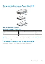
Page 23: ...Component Height U Space Depth in cm Engine 4U 30 76 2 DAE 2U 20 50 8 SPS 2U 28 71 2 NOTE Component dimensions do not include cable connections and bend radii Do not use these component dimensions for rack sizing For information about the total envelope required for the platform see Third Party Racking Option for PowerMax 2000 on page 50 Component dimensions PowerMax 8000 The following figure and ...

Page 24: ...nt Height U Space Depth in cm Engine 4U 30 76 2 Engine CMA area 4U 10 26 4 DAE 2U 20 50 8 SPS 2U 28 71 2 MIBE 1U Two units required per system for 2U total 24 61 Ethernet tray 1U 34 86 4 Service tray 1U 17 43 2 NOTE Component dimensions do not include cable connections and bend radii Do not use these component dimensions for rack sizing For information about the total envelope required for the pla...

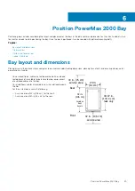
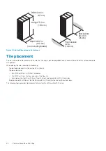
Page 25: ...oom involves understanding dimensions planning for cutouts and ensuring clearance for power and host cables On nonraised floors cables are routed overhead An overhead routing bracket is available for purchase to allow easier access of overhead cables into the bay On raised floors cables are routed across the subfloor beneath the tiles For the system bay ensure the following A service area of 42 in...

Page 26: ... and cable management When placing the array consider the following Typical floor tiles are 24 in 61 cm by 24 in 61 cm Typical cutouts are 8 in 20 3 cm by 6 in 15 2 cm maximum 9 in 22 9 cm from the front and rear of the floor tile Centered on the tiles 9 in 22 9 cm from the front and rear and 8 in 20 3 from sides Service area of 42 in 106 cm for the front and 30 in 76 cm for the rear on the system...

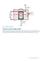
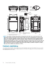
Page 27: ...abinet bottom includes four caster wheels The front wheels are fixed the two rear casters swivel in a 1 75 inch diameter Swivel position of the caster wheels will determine the load bearing points on your site floor but does not affect the cabinet footprint Once you have positioned leveled and stabilized the cabinet the four leveling feet determine the final load bearing points on your site floor ...

Page 28: ...ble of supporting the system weight whether the system is configured directly on the data center floor or on a raised floor supported by the data center floor Failure to comply with these floor loading requirements could result in severe damage to the system the raised floor subfloor site floor and the surrounding infrastructure Notwithstanding anything to the contrary in any agreement between the...

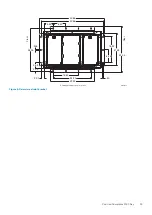
Page 29: ... 88 40 88 8 30 5 92 28 03 438 3 55 2 00 2 00 16 60 24 90 50 8 46 16 92 21 25 30 03 EMC2856 Front Rear All measurements are in inches 29 23 Figure 6 Seismic restraint bracket Position PowerMax 2000 Bay 29 ...

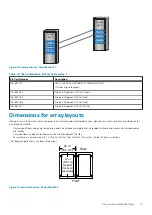
Page 30: ...ys require dispersed cable and optics kits When systems are ordered as dispersed the dispersed bay is shipped with two side skins installed Adjacent layouts PowerMax 8000 PowerMax 8000 systems with adjacent layouts position System Bay 1 next to System Bay 2 The following figure shows the adjacent layout The side skin on System Bay 1 that is adjacent to System Bay 2 is moved to the outer side of Sy...

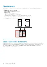
Page 31: ...ay layouts Placing arrays in the data center or computer room involves understanding dimensions planning for cutouts and ensuring clearance for power and host cables On nonraised floors cables are routed overhead An overhead routing bracket is provided to allow easier access of overhead cables into the bay On raised floors cables are routed across the subfloor beneath the tiles Ensure there is a s...

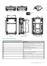
Page 32: ... on the system bays The following figure provides tile placement information for all arrays with doors Rear A A System bay System bay Front F l o o r T i l e Figure 10 Placement with floor tiles PowerMax 8000 Caster and leveler dimensions The bottom of each bay includes four caster wheels The front wheels are fixed the two rear casters swivel in a 1 75 in diameter Swivel position of the caster whe...

Page 33: ...s diagram key Description 1 Minimum 17 102 and maximum 20 58 distances based on the swivel position of the caster wheel 2 Right front corner detail Dimension 3 628 to the center of caster wheel from surface 3 Diameter 1 750 of caster wheel swivel 4 Outer surface of rear door 5 6 Diameter 1 75 of swivel see detail 3 7 Bottom view of leveling feet 8 Maximum 32 620 distance based on swivel position o...

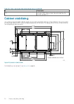
Page 34: ... mounting bolts The seismic restraint bracket provides protection from moving and tipping helping to prevent the cabinet from tipping while you service cantilevered levels or from rolling during minor seismic events 46 00 28 03 2 00 2 00 48 00 9 97 5 92 21 25 50 34 23 29 91 9 97 19 94 8 46 16 92 3 55 63 30 03 All measurements are in inches CL5446 Figure 12 Seismic restraint bracket For information...

Page 35: ...rear top cover of the bay with the ceiling routing top cover which allows the power cables inside the machine to be routed out through the top A second option is to drop the power cables down the hinge side to the bottom and route them inside the machine The cables should be dressed to allow all doors to open freely and space should be provisioned accordingly to accommodate an adjacent cabinet If ...

Page 36: ...rray If both power drops to a bay are connected to the same PDU incorrectly a DU event will result during normal data center maintenance when the PDU is switched off The label on the power cables depicts the correct connection The electrician should pay particular attention to how each PDU receives power from each UPS within the data center because it is possible to create a scenario where turning...

Page 37: ...llowing table describes the power cords for single phase power transmission Each power cord model contains two 2 15FT 4 57M cords Single phase powered systems use a jumper PN 038 004 186 See PowerMax 2000 line cord and jumper configurations on page 39 and PowerMax 8000 line cord and jumper configurations on page 41 for line cord and jumper configurations NOTE The ordering system defaults to one of...

Page 38: ...Black 038 004 863 Gray N America INTL 32 AMP 3PHASE WYE ABL Sursum S52S30A or Hubbell C530P6S Hubbell is US and international dual rated 30 A 32 A ABL Sursum K52S30A or Hubbell C530C6S PowerMax 2000 EH PC3YAFLA PowerMax 8000 EZ PC3YAFLA NOTE These models are being phased out and replaced with models EH PC3YAFLAI and EZ PC3YAFLAI 038 002 499 Black 038 002 500 Gray 32A 3PHASE WYE CORD SET IEC309 AME...

Page 39: ...CBL HBL HBL 3D Hubbell CS 8365L Hubbell CS 8364 PowerMax 2000 EH PCBL3DHR PowerMax 8000 EZ PCBL3DHR 038 004 433 Black 038 004 434 Gray PWR CBL HBL RSTOL 3D Russellstoll 9P54U2 Russellstoll 9C54U2 PowerMax 2000 line cord and jumper configurations Three phase power For a single PowerMax 2000 system in a rack on three phase power a line cord in the P1 outlet energizes PDU outlets 1 18 on circuit brea...

Page 40: ...ocation from to Circuit breakers PDU outlets PowerBrick 2 Upper System DAE 4 P6 No additional power jumpers required 11 12 31 37 DAE 3 SPS 2A 2B PowerBrick 1 Upper System DAE 2 P4 J4 P5 PN 038 004 186 This jumper must be installed in the field with a second system 7 10 19 30 DAE 1 SPS 3A 3B PowerBrick 2 Lower System DAE 4 P3 No additional power jumpers required 5 6 13 18 DAE 3 SPS 2A 2B PowerBrick...

Page 41: ...E is pre installed at the factory and should not be removed Table 28 PowerMax 8000 line cord configurations three phase PowerBrick Components Line cord location PowerBrick 4 8 DAE 6 No additional line cords required SPS 4A 4B PowerBrick 3 7 DAE 5 No additional line cords required DAE 4 SPS 3A 3B PowerBrick 2 6 DAE 3 No additional line cords required SPS 2A 2B PowerBrick 1 5 DAE 2 P1 DAE 1 MIBE A B...

Page 42: ...following locations J1 P2 J5 P6 Each line cord energizes the circuit breakers and corresponding PDU outlets as follows Table 29 PowerMax 8000 line cord configurations single phase PowerBrick Components Line cord location Circuit breakers PDU outlets PowerBrick 4 8 DAE 6 No additional line cords required SPS 4A 4B PowerBrick 3 7 DAE 5 P5 9 12 25 37 DAE 4 SPS 3A 3B PowerBrick 2 6 DAE 3 P3 5 6 13 18 ...

Page 43: ...Figure 16 Customer input power outlet single phase Power Cabling Cords and Connectors 43 ...

Page 44: ...ems Number of racks in system Grounding required Reference 1 No Grounding a single bay on page 44 2 Yes Chassis to chassis grounding on page 45 Grounding a single bay Equipment correctly installed within the cabinet is grounded through the AC power cables and connectors In general supplemental grounding is not required for a single bay If your site requires external grounding for example to a comm...

Page 45: ...N 106 562 209 to provide chassis to chassis grounding The kit provides straps for both the front and rear of the cabinets Both straps must be installed to provide chassis to chassis grounding In customer rack systems mechanisms for tying racks together to provide the ground connection can vary based on the rack provided by the customer and site facility preference PN 106 562 209 is a rack to rack ...

Page 46: ...led as a field upgrade option PowerMax 2000 systems in a Dell EMC rack must conform to the following requirements Lower system 1U 20U Upper system 21U 40U The following diagrams illustrate possible configurations for two PowerMax 2000 systems in a Dell EMC rack Two PowerMax 2000 systems 1 PowerBrick 1 PowerBrick configuration Engine 1 DAE 1 DAE 2 SPS SPS U10 Engine 1 DAE 1 DAE 2 SPS SPS U21 A B C ...

Page 47: ...ax 2000 systems 2 PowerBrick 2 PowerBrick configuration Engine 1 DAE 1 DAE 2 SPS SPS Engine 2 DAE 3 DAE 4 SPS SPS 20U Engine 1 DAE 1 DAE 2 SPS SPS Engine 2 DAE 3 DAE 4 SPS SPS U21 A B Figure 19 Two PowerMax 2000 systems 2 PowerBrick 2 PowerBrick configuration Table 31 Stack up key A Lower system B Upper system Dell EMC Racking for PowerMax 2000 47 ...

Page 48: ...2 SPS SPS SPS SPS Engine 2 DAE 3 DAE 4 Engine 1 DAE 1 DAE 2 SPS SPS U21 A B C Figure 20 Two PowerMax 2000 systems 2 PowerBrick 1 PowerBrick configuration Table 32 Stack up key A Lower system B Upper system C Space for second PowerBrick upper system 48 Dell EMC Racking for PowerMax 2000 ...

Page 49: ...t be properly positioned within the rack in accordance with the following rules Dell EMC equipment should stack from the bottom of the rack Customer equipment stacks from the top of the rack A system must exist within contiguous space Customer equipment must be above a PowerMax 2000 system and not interwoven within the system All customer equipment must be electrically isolated and powered by the ...

Page 50: ...alled one on each side Each must be connected to customer power The customer rack must support a minimum 850 lbs 385 kg of weight plus the weight of any third party components within the rack NOTE The customer must ensure that floor load bearing requirements are met After installation components and cables within the rack cannot be moved to available space in a different rack or to a different loc...

Page 51: ...n in the tables in PowerMax 2000 power consumption and outlet requirements on page 51 for the specific maximum configuration The PDU is mounted symmetrically on each side of a rack If the customer requires power to be supplied from overhead Dell EMC recommends one of the following Option 1 If possible route the power cables from inside the machine through the top of the rack Option 2 Drop the powe...

Page 52: ... the array J Figure 22 PowerMax 2000 Minimum requirements for third party racks with rear facing PDUs Key Description Minimum distance in cm A Minimum depth of the rack Total value of B C D in the diagram B Distance between front surface of the rack post and the NEMA rail C Distance between the NEMA rails 24 61 D Distance between the rear NEMA rails to the exterior rear surface of the rack 14 35 6...

Page 53: ... may encroach into the service area and make serviceability more difficult than rear facing PDUs Figure 23 PowerMax 2000 Minimum requirements for third party racks with inward facing PDUs Key Description Minimum distance in cm A Minimum depth of the rack Total value of B J G K L in the diagram B Distance between front surface of the rack post and the NEMA rail C Distance between the NEMA rails 24 ...

Page 54: ...he distance between the back surface of the door and the front surface of the vertical NEMA rail Space is required to provide clearing for bezel airflow 2 5 6 4 J Space required for enclosures rails and cable management arms 37 94 K PDU width L Distance from the equipment enclosure area to the front facing side of the PDU 0 1 0 26 M AC cable bend radius The bend radius is expected to encroach into...

Page 55: ... be provided for each system bay NOTE The customer must ensure floor load bearing requirements are met Components and cables installed in customer racks must conform to these configuration rules The stack up must adhere to the standard configuration Components and cables within a system bay can not be moved to available space in a different bay or to a different location within the same bay The sy...

Page 56: ...symmetrically on each side of a rack If the customer requires power to be supplied from overhead Dell EMC recommends one of the following Option 1 If possible route the power cables from inside the machine through the top of the rack Option 2 Drop the power cables down the hinge side to the bottom and route them inside the machine In either case dress the power cables to the side walls so they do ...

Page 57: ... total power consumption 35 C VA Zone A Zone B Zone A Zone B PowerBrick 8 DAE 6 1 1 681 Engine 8 SPS 1 1 1860 TOTALS FOR PowerBrick 8 2 2 2541 PowerBrick 7 DAE 5 1 1 584 DAE 4 1 1 681 Engine 7 SPS 1 1 1860 TOTALS FOR PowerBrick 7 3 3 3125 PowerBrick 6 Engine 6 SPS 1 1 1860 DAE 3 1 1 681 TOTALS FOR PowerBrick 6 2 2 2541 PowerBrick 5 Engine 5 SPS 1 1 1860 DAE 2 1 1 584 DAE 1 1 1 681 TOTALS FOR Power...

Page 58: ...nd route customer host cables 6 15 3 H PDU width I If a front door exists this is the distance between the back surface of the door and the front surface of the vertical NEMA rail Space is required to provide clearing for bezel airflow 2 5 6 4 J Space required for enclosures rails and cable management arms 41 104 2 K Distance between the rack wall and the NEMA rail spacing This space must be large...

Page 59: ...is required to determine the minimum width of the rack The equation can be thought of as E H H M M G Distance between the rear facing surface of the PDU and the surface of the rack post This space must be large enough to house power cables and route customer host cables 3 7 7 H PDU depth from rack sidewall I If a front door exists this is the distance between the back surface of the door and the f...

Page 60: ... routing cover Table 38 Overhead routing models Model Top routing kit PowerMax 2000 EH TOP KIT PowerMax 8000 EZ TOP KIT Securing kits The securing kits contain heavy brackets plus hardware used to attach the brackets to the frames of the system bays The brackets are attached to the floor using bolts that engage the flooring substructure provided by the customer The Dell EMC VMAX Securing Kit Insta...

Page 61: ...ss the subfloor or ceiling to connect the SIB and MM components in System Bay 2 to the MIBE and Ethernet switches in System Bay 1 Table 40 Fabric dispersion kits for System Bay 2 Kit Part Number Description 106 887 147 VMAX EVEREST DISPERSION TRANSCEIVER KIT 1 kit per engine required 106 887 034 Engine 5 Dispersion Kit 30m Green 106 887 035 Engine 6 Dispersion Kit 30m Blue 106 887 036 Engine 7 Dis...

Page 62: ...able there is a higher risk of data unavailability should a power failure occur including individual phase loss occurring in both power zones Before connecting external AC power to storage bays verify that the bays have been placed in their final position as explained in the installation guide Customer s PDU 1 Customer s PDU 2 Circuit breakers on Circuit breakers on Circuit breakers Numbers 27 28 ...

Page 63: ...mer s electrician Procedure A Task 1 Customer s electrician About this task NOTE This task is performed by the customer s electrician Steps 1 Verify that the customer supplied AC source voltage output on each customer supplied PDU is within the AC power specification shown in AC power specifications on page 70 Measure the voltage output of each power cable as shown in Figure 28 Circuit breakers ON...

Page 64: ...breakers OFF No AC power Procedure A Task 2 Dell EMC Customer Engineer Before connecting power to the PowerMax system make sure that the power for both zone A and zone B are turned OFF This task is performed by the Dell EMC Customer Engineer NOTE Do not connect storage bay power zone A and power zone B to the same customer supplied PDU The customer will lose power redundancy and risk Data Unavaila...

Page 65: ...reakers CBs Customer s Power Source 2 Circuit Breakers CBs 046 001 749_01 Figure 30 Power zone connections Attaching line cord identification labels Steps 1 Select the appropriate line cord identification label from the install kit Table 42 Line cord identification label location Dell EMC racks Label part number Input power Location 046 007 880 Single phase OPEN ME FIRST KIT PN 106 887 026 046 008...

Page 66: ...rt the customer 2 Compare the numbers on the customer supplied power cables for each storage bay to verify that power zone A and power zone B are powered by a different customer supplied PDU 3 Do one of the following to connect power zone A and power zone B in each bay For single phase power Connect customer supplied PDU power cables to the storage bay by connecting to the bay s AC input line cord...

Page 67: ...er Connect customer supplied PDU power cables to the storage bay by connecting to the bay s AC input line cords for power zone A and power zone B as shown below Customer s PDU 1 Zone B AC input line cord B Mating connector or customer supplied cable Customer s PDU 2 Zone A AC input line cord A Mating connector or customer supplied cable Cable connectors are shown as they exit the bottom rear of th...

Page 68: ...by a single PDU customer supplied PDU 2 The wiring must be corrected before moving on to the next step 2 Turn OFF the relevant circuit breakers in customer supplied PDU 2 Verify that the power supply and or SPS LEDs that turned green in the previous step changed from green to OFF and or flashing yellow The yellow SPS lights flash for a maximum of 5 minutes NOTE Power supplies connected to an SPS c...

Page 69: ...cedure C Obtain customer verification About this task Perform this procedure if the three conditions listed below are true The customer supplied PDU source cables are already plugged into the storage bay PDU You have no access to the area below the raised floor The customer s electrician is not available at the installation site Steps 1 Have the customer verify that their electrician has complied ...

Page 70: ... connection tag to the main AC power cable connected to zone A and B Place the label close to the plug but on the side of the rack where it will not interfere with any rails For single phase power Using plastic ties attach the PDU connection tag to the P1 AC power cable connected to zone A and B Place the label close to the plug but on the side of the rack where it will not interfere with any rail...

Page 71: ...national Australian Specification North American 4 wire connection 3 L 1 G a International 5 wire connection 3 L 1 N 1 G a Input voltageb 200 240 VAC 10 L L nom 220 240 VAC 10 L N nom Frequency 50 60 Hz 50 60 Hz Circuit breakers 50 A 32 A Power zones Two Two Minimum power requirements at customer site One 50 A three phase line cord per power zone One 32 A three phase line cord per power zone a L l...

Reviews: