Position PowerMax 2000 Bay
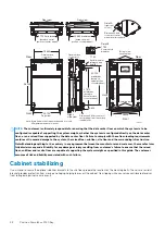
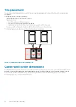
Positioning bays includes considering the layout and placement of the bays in the data center and placement on tiles. Each cabinet sits on
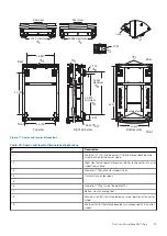
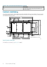
four caster wheels to aid in positioning the bay. Once the bay is positioned it can be secured with optional mounting bolts.
Topics:
•
•
•
•
Bay layout and dimensions
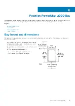
Placing arrays in the data center or computer room involves understanding dimensions, planning for cutouts, and ensuring clearance for
power and host cables.
•
On nonraised floors, cables are routed overhead. An overhead
routing bracket is available for purchase to allow easier access
of overhead cables into the bay.
•
On raised floors, cables are routed across the subfloor beneath
the tiles.
•
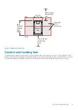
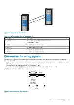
For the system bay, ensure the following:
○
A service area of 42 in (106 cm) for the front.
○
A service area of 30 in (76 cm) for the rear.
Front
Rear
24.02 in.
(61.01 cm)
24 in.
(61 cm)
Bezel
39.37 in.
(100.0 cm)
rack only
42 in.
(106 cm)
Includes
front
bezels
42 in. (106 cm)
service area
30 in. (76 cm)
service area
6
Position PowerMax 2000 Bay
25

