background image

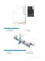
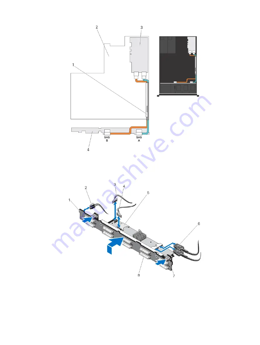
Figure 51. Cabling diagram—2.5 inch (x8) systems

1

cable retention bracket

2

system board

3

SAS controller card

4

SAS backplane 

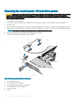
Figure 52. Removing and installing the 2.5 inch (x10) hard-drive backplane

1

SAS backplane 

2

backplane power cable 

3

SD signal cable

4

backplane signal cable

Installing and removing system components

85

Summary of Contents for PowerEdge R620

Page 1: ...Dell PowerEdge R620 Owner s Manual Regulatory Model E16S Series Regulatory Type E16S001 ...

Page 2: ...age to hardware or loss of data and tells you how to avoid the problem WARNING A WARNING indicates a potential for property damage personal injury or death 2012 2018 Dell Inc or its subsidiaries All rights reserved Dell EMC and other trademarks are trademarks of Dell Inc or its subsidiaries Other trademarks may be trademarks of their respective owners 2018 11 Rev A06 ...

Page 3: ... 20 System Setup options 21 System Setup Main screen 21 System BIOS screen 21 System information screen 22 Memory Settings screen 22 Processor Settings Screen 23 SATA settings screen details 24 Boot Settings screen 25 Integrated devices screen 25 Serial communications screen 26 System Profile Settings screen 26 System security screen 27 Miscellaneous settings 28 System and setup password features ...

Page 4: ...Hard drives 48 Removing a 2 5 inch hard drive blank 49 Installing A 2 5 Inch Hard Drive Blank 49 Removing a hot swap hard drive 49 Installing a hot swappable hard drive or solid state drive 50 Removing a hard drive from a hard drive carrier 51 Installing a hard drive or solid state drives into a hard drive carrier 52 Optical drive optional 52 Removing the optical drive 52 Installing the optical dr...

Page 5: ...r Supply 76 Installing A DC Power Supply 77 Removing The Power Supply Blank 78 Installing The Power Supply Blank 78 System battery 78 Replacing the system battery 78 Hard drive backplane 80 Removing the hard drive backplane 80 Installing the hard drive backplane 86 Control panel assembly 87 Removing the control panel board 8 hard drive system 87 Installing the control panel board 8 hard drive syst...

Page 6: ...up unit 102 Troubleshooting a hard drive 103 Troubleshooting a storage controller 103 Troubleshooting expansion cards 104 Troubleshooting processors 104 5 Using system diagnostics 105 Dell Online Diagnostics 105 Dell Embedded System Diagnostics 105 When to use the Embedded System Diagnostics 105 Running the Embedded System Diagnostics 105 System diagnostics controls 106 6 Jumpers and connectors 10...

Page 7: ...m NOTE On ACPI compliant operating systems turning off the system using the power button causes the system to perform a graceful shutdown before power to the system is turned off 2 NMI button Used to troubleshoot software and device driver errors when running certain operating systems This button can be pressed using the end of a paper clip Use this button only if directed to do so by qualified su...

Page 8: ...eration The LCD lights amber when the system needs attention and the LCD panel displays an error code followed by descriptive text NOTE If the system is connected to AC power and an error is detected the LCD lights amber regardless of whether the system is turned on or off 9 Information tag A slide out label panel which allows you to record system information such as Service Tag NIC MAC address an...

Page 9: ...press and hold the system ID button for more than five seconds to enter BIOS progress mode To reset the iDRAC if not disabled in F2 iDRAC setup press and hold the button for more than 15 seconds 6 Mini USB connector Allows you to connect USB devices to the system The port is USB 2 0 compliant 7 Hard drives 10 Up to ten 2 5 inch hot swappable hard drives 8 Information tag A slide out label panel wh...

Page 10: ...ssages Press one of the three navigation buttons Select Left or Right to view the Home screen To navigate to the Home screen from another menu continue to select the up arrow until the Home icon is displayed and then select the Home icon From the Home screen press the Select button to enter the main menu Setup menu NOTE When you select an option in the Setup menu you must confirm the option before...

Page 11: ...g iDRAC from the LCD panel The LCD panel on the front bezel optional has these three buttons for selecting changing and entering data Enter Move the selection to the left or decrease the value depending on the context Move the selection to the right or increase the value depending on the context We can assign iDRAC IP address by using LifeCycle controller BIOS and from the LCD panel NOTE Changing ...

Page 12: ...gnostic indicators on the system front panel display error status during system startup NOTE The diagnostic indicators are not present if the system is equipped with an LCD display NOTE The diagnostic indicators are present only on the 10 hard drive system The following section describes system conditions and possible corrective actions associated with these indicators Electrical indicator Conditi...

Page 13: ...tus indicator on the right side does not function and remains off Drive Status Indicator Pattern RAID Only Condition Blinks green two times per second Identifying drive or preparing for removal Off Drive ready for insertion or removal NOTE The drive status indicator remains off until all hard drives are initialized after the system is turned on Drives are not ready for insertion or removal during ...

Page 14: ... Allows you to connect the optional system status indicator assembly through the optional cable management arm 3 iDRAC7 Enterprise port Dedicated management port NOTE The port is available for use only if the iDRAC7 Enterprise license is installed on your system 4 Serial connector Allows you to connect a serial device to the system 5 PCIe expansion card slot riser 2 Allows you to connect a PCIe ex...

Page 15: ...iDRAC setup press and hold for more than 15 seconds 2 System identification connector Allows you to connect the optional system status indicator assembly through the optional cable management arm 3 iDRAC7 Enterprise port Dedicated management port NOTE The port is available for use only if the iDRAC7 Enterprise license is installed on your system 4 PCIe expansion card slot riser 1 Allows you to con...

Page 16: ...indicator is green The NIC is connected to a valid network at its maximum port speed 1 Gbps or 10 Gbps Link indicator is amber The NIC is connected to a valid network at less than its maximum port speed Activity indicator is blinking green Network data is being sent or received Power Indicator Codes Each AC power supply has an illuminated translucent handle and each DC power supply when available ...

Page 17: ...place only the power supply with the flashing indicator Swapping the opposite power supply to make a matched pair can result in an error condition and unexpected system shutdown To change from a High Output configuration to a Low Output configuration or vice versa you must power down the system CAUTION AC power supplies support both 220 V and 110 V input voltages with the exception of Titanium pow...

Page 18: ...ithin this document or as a separate document The Getting Started Guide provides an overview of setting up your system and technical specifications This document is available online at dell com support manuals The rack documentation included with your rack solution describes how to install your system into a rack if required Any media that ships with your system that provides documentation and too...

Page 19: ...t Execution Environment PXE boot From System Setup you can Change the NVRAM settings after you add or remove hardware View the system hardware configuration Enable or disable integrated devices Set performance and power management thresholds Manage system security You can access System Setup using the Standard graphical browser which is enabled by default Text browser which is enabled using Consol...

Page 20: ...nd can only be installed from the BIOS boot mode For the latest information about supported operating systems go to Dell com ossupport Entering System Setup 1 Turn on or restart your system 2 Press F2 immediately after you see the following message F2 System Setup If your operating system begins to load before you press F2 wait for the system to finish booting and then restart your system and try ...

Page 21: ...as the system model name BIOS version Service Tag and so on Memory Settings Displays information and options related to installed memory Processor Settings Displays information and options related to the processor such as speed cache size and so on SATA Settings Displays options to enable or disable the integrated SATA controller and ports Boot Settings Displays options to specify the boot mode BI...

Page 22: ...e system System Memory Speed Displays the system memory speed System Memory Voltage Displays the system memory voltage Video Memory Displays the amount of video memory System Memory Testing Specifies whether system memory tests are run during system boot Options are Enabled and Disabled By default the System Memory Testing option is set to Disabled Memory Operating Mode Specifies the memory operat...

Page 23: ...led Adjacent Cache Line Prefetch Allows you to optimize the system for applications that require high utilization of sequential memory access By default the Adjacent Cache Line Prefetch option is set to Enabled You can disable this option for applications that require high utilization of random memory access Hardware Prefetcher Allows you to enable or disable hardware prefetcher By default the Har...

Page 24: ...OTE The following settings are displayed for each processor installed in the system Family Model Stepping Displays the family model and stepping of the processor as defined by Intel Brand Displays the brand name reported by the processor Level 2 Cache Displays the total L2 cache Level 3 Cache Displays the total L3 cache Number of Cores Displays the number of cores per processor SATA settings scree...

Page 25: ...ne time boot from a selected device Integrated devices screen Menu Item Description Integrated RAID Controller Allows you to enable or disable the integrated RAID controller By default the Integrated RAID Controller option is set to Enabled User Accessible USB Ports Allows you enable or disable the user accessible USB ports Selecting Only Back Ports On disables the front USB ports and selecting Al...

Page 26: ...tion option is set to On without Console Redirection Serial Port Address Allows you to set the port address for serial devices By default the Serial Port Address option is set to Serial Device 1 COM2 Serial Device 2 COM1 NOTE Only Serial Device 2 can be used for Serial Over LAN SOL To use console redirection by SOL configure the same port address for console redirection and the serial device Exter...

Page 27: ...ets the memory patrol scrub frequency This option is set to Standard by default Memory Refresh Rate Sets the memory refresh rate to either 1x or 2x This option is set to 1x by default Memory Operating Voltage Sets the DIMM voltage selection When set to Auto the system automatically sets the system voltage to the optimal setting based on the DIMM capacity and the number of DIMMs installed By defaul...

Page 28: ... is set to Enabled NMI Button Allows you to enable or disable the NMI button on the front of the system By default the NMI Button option is set to Disabled AC Power Recovery Allows you to set how the system reacts after AC power is restored to the system By default the AC Power Recovery option is set to Last NOTE Set the AC Power Recovery option to On or Last to enable or disable the AC Power Reco...

Page 29: ...or disables the System Password and Setup Password features For more information on the password jumper settings see System board jumper settings NOTE You can assign a new System Password or Setup Password or change an existing System Password or Setup Password only when the password jumper setting is enabled and Password Status is set to Unlocked If the Password Status is set to Locked you cannot...

Page 30: ... you to reenter the new password If you delete the system password or setup password a message prompts you to confirm the deletion Using your system password to secure your system If you have assigned a setup password the system accepts your setup password as an alternate system password 1 Turn on or reboot your system 2 Type the system password and press Enter When Password Status is set to Locke...

Page 31: ...applicable Tab Moves to the next focus area NOTE For the standard graphics browser only Esc Moves to the previous page till you view the main screen Pressing Esc in the main screen exits the Boot Manager and proceeds with system boot F1 Displays the System Setup help file NOTE For most of the options any changes that you make are recorded but do not take effect until you restart the system Boot Ma...

Page 32: ... information about setting up the Dell Lifecycle Controller configuring hardware and firmware and deploying the operating system see the Dell Lifecycle Controller documentation at Dell com idracmanuals iDRAC Settings utility The iDRAC settings utility is an interface to set up and configure the iDRAC parameters by using UEFI You can enable or disable various iDRAC parameters by using the iDRAC set...

Page 33: ...ed Offset NOTE When the User Option is set to the default Auto setting the user option cannot be modified 3 Set the Maximum Air Exhaust Temperature or the Fan Speed Offset fields 4 Click Back Finish Yes Using the system setup and boot manager 33 ...

Page 34: ...pper wire AMP 90871 1 hand crimping tool or equivalent NOTE Use alpha wire part number 3080 or equivalent 65 30 stranding Front bezel optional The front bezel is attached to the front side of the system and prevents accidents while removing the hard drive or when pressing the reset or power button The front bezel can also be locked for additional security Removing the front bezel 1 Unlock the keyl...

Page 35: ...tem NOTE It is recommended that you always use an antistatic mat and antistatic strap while working on components inside the system 1 Turn off the system and attached peripherals and disconnect the system from the electrical outlet 2 Rotate the latch release lock counter clockwise to the unlocked position 3 Lift the latch on top of the system and slide the cover back 4 Grasp the cover on both side...

Page 36: ...ctrical outlet and turn the system on including any attached peripherals Inside the system CAUTION Many repairs may only be done by a certified service technician You should only perform troubleshooting and simple repairs as authorized in your product documentation or as directed by the online or telephone service and support team Damage due to servicing that is not authorized by Dell is not cover...

Page 37: ...g shroud 6 power supplies 2 7 chassis intrusion switch 8 riser card 3 9 network daughter card 10 riser card 2 11 storage controller card 12 network daughter card cooling shroud 13 DIMMs 24 14 heat sink for processor 2 15 hard drive backplane 16 control panel 17 hard drives 8 18 optical drive optional Installing and removing system components 37 ...

Page 38: ...ased cooling Removing the cooling shroud CAUTION Many repairs may only be done by a certified service technician You should only perform troubleshooting and simple repairs as authorized in your product documentation or as directed by the online or telephone service and support team Damage due to servicing that is not authorized by Dell is not covered by your warranty Read and follow the safety ins...

Page 39: ...4 Close the system 5 Reconnect the system to its electrical outlet and turn the system on including any attached peripherals System memory Your system supports DDR3 unbuffered ECC DIMMs ECC UDIMMs registered DIMMs RDIMMs and load reduced DIMMs LRDIMMs It supports DDR3 and DDR3L voltage specifications NOTE MT s indicates DIMM speed in MegaTransfers per second Memory bus operating frequency can be 1...

Page 40: ...2 Memory channels Processor Channel 0 Channel 1 Channel 2 Channel 3 Processor 1 slots A1 A5 and A9 slots A2 A6 and A10 slots A3 A7 and A11 slots A4 A8 and A12 Processor 2 slots B1 B5 and B9 slots B2 B6 and B10 slots B3 B7 and B11 slots B4 B8 and B12 The following table shows the memory populations and operating frequencies for the supported configurations 40 Installing and removing system componen...

Page 41: ...se levers the third DIMM slot in the channel with green release levers cannot be populated Up to three LRDIMMs can be populated regardless of rank count Populate DIMM sockets only if a processor is installed For single processor systems sockets A1 to A12 are available For dual processor systems sockets A1 to A12 and sockets B1 to B12 are available Populate all sockets with white release tabs first...

Page 42: ...s not impose any specific slot population requirements Memory sparing NOTE To use memory sparing this feature must be enabled in System Setup In this mode one rank per channel is reserved as a spare If persistent correctable errors are detected on a rank the data from this rank is copied to the spare rank and the failed rank is disabled With memory sparing enabled the system memory available to th...

Page 43: ...s section NOTE 16 GB quad rank RDIMMs are not supported NOTE 1R 2R and 4R in the following tables indicate single dual and quad rank DIMMs respectively Table 4 Memory configurations single processor System Capacity in GB DIMM Size in GB Number of DIMMs DIMM Rank Organization and Frequency DIMM Slot Population 2 2 1 1R x8 1333 MT s 1R x8 1600 MT s A1 4 2 2 1R x8 1333 MT s 1R x8 1600 MT s A1 A3 8 2 ...

Page 44: ...RDIMM x4 1333 MT s A1 A2 A3 A4 A5 A6 A7 A8 A9 A10 A11 A12 768 64 12 LRDIMM x4 1333 MT s A1 A2 A3 A4 A5 A6 A7 A8 A9 A10 A11 A12 Table 5 Memory configurations two processors System Capacity in GB DIMM Size in GB Number of DIMMs DIMM Rank Organization and Frequency DIMM Slot Population 16 2 8 1R x8 1333 MT s 1R x8 1600 MT s A1 A2 A3 A4 B1 B2 B3 B4 32 2 16 1R x8 1333 MT s A1 A2 A3 A4 A5 A6 A7 A8 B1 B2...

Page 45: ...B3 B4 B5 B6 NOTE 16 GB DIMMs must be installed in slots numbered A1 A2 A3 A4 B1 B2 B3 and B4 and 8 GB DIMMs must be installed in slots A5 A6 B5 and B6 192 8 24 2R x4 1333 MT s A1 A2 A3 A4 A5 A6 A7 A8 A9 A10 A11 A12 B1 B2 B3 B4 B5 B6 B7 B8 B9 B10 B11 B12 16 12 2R x4 1333 MT s 2R x4 1600 MT s A1 A2 A3 A4 A5 A6 B1 B2 B3 B4 B5 B6 256 16 16 2R x4 1333 MT s 2R x4 1600 MT s A1 A2 A3 A4 A5 A6 A7 A8 B1 B2 ...

Page 46: ...by Dell is not covered by your warranty Read and follow the safety instructions that are shipped with your product CAUTION To ensure proper cooling memory module blanks must be installed in any memory socket that is not occupied Remove memory module blanks only if you intend to install memory modules in those sockets 1 Turn off the system including any attached peripherals and disconnect the syste...

Page 47: ...y module blanks must be installed in any memory socket that is not occupied Remove memory module blanks only if you intend to install memory modules in those sockets 1 Turn off the system including any attached peripherals and disconnect the system from the electrical outlet 2 Open the system 3 If applicable remove the cooling shroud 4 Locate the memory module sockets CAUTION Handle each memory mo...

Page 48: ...ay not be installed properly Repeat step 4 through step 7 of this procedure checking to ensure that the memory modules are firmly seated in their sockets 14 Run the appropriate diagnostic test For more information see Using System Diagnostics Hard drives All hard drives connect to the system board through the hard drive backplane Hard drives are supplied in hot swappable hard drive carriers that f...

Page 49: ...perating system supports hot swap drive installation See the documentation supplied with your operating system 1 From the management software prepare the hard drive for removal Wait until the indicators on the hard drive carrier signal that the hard drive can be removed safely For more information see the documentation for the storage controller If the hard drive is online the green activity fault...

Page 50: ...e that your operating system supports hot swap drive installation See the documentation supplied with your operating system CAUTION When a replacement hot swappable drive is installed and the system is powered on the drive automatically begins to rebuild Ensure that the replacement drive is blank or contains data that you wish to overwrite Any data on the replacement drive is immediately lost afte...

Page 51: ...r handle Removing a hard drive from a hard drive carrier 1 Remove the screws from the slide rails on the hard drive carrier 2 Lift the hard drive out of the hard drive carrier Figure 22 Removing and Installing a Hard Drive Into a Hard Drive Carrier 1 hard drive carrier 2 hard drive Installing and removing system components 51 ...

Page 52: ...pairs may only be done by a certified service technician You should only perform troubleshooting and simple repairs as authorized in your product documentation or as directed by the online or telephone service and support team Damage due to servicing that is not authorized by Dell is not covered by your warranty Read and follow the safety instructions that are shipped with your product NOTE This p...

Page 53: ...to servicing that is not authorized by Dell is not covered by your warranty Read and follow the safety instructions that are shipped with your product NOTE This procedure applies only to the eight hard drive system 1 If installed remove the front bezel 2 Turn off the system including any attached peripherals and disconnect the system from its electrical outlet 3 Open the system 4 Align the optical...

Page 54: ...eshooting and simple repairs as authorized in your product documentation or as directed by the online or telephone service and support team Damage due to servicing that is not authorized by Dell is not covered by your warranty Read and follow the safety instructions that are shipped with your product CAUTION The cooling fans are hot swappable To maintain proper cooling while the system is on repla...

Page 55: ... then specify the USB memory key in the boot sequence in the System Setup NOTE To locate the internal USB connector J_USB_INT on the system board see System Board Connectors Replacing The Internal USB Key CAUTION Many repairs may only be done by a certified service technician You should only perform troubleshooting and simple repairs as authorized in your product documentation or as directed by th...

Page 56: ...ee pcie expansion cards Riser PCIe Slot Processor Connection Height Length Link Width Slot Width 1 1 Processor 2 Low Profile Half Length x8 x16 1 2 Processor 2 Low Profile Half Length x16 x16 3 3 Processor 1 Low Profile Half Length x16 x16 NOTE Both the processors must be installed to use riser 1 slots Table 7 Systems supporting two pcie expansion cards Riser PCIe Slot Processor Connection Height ...

Page 57: ...ubleshooting and simple repairs as authorized in your product documentation or as directed by the online or telephone service and support team Damage due to servicing that is not authorized by Dell is not covered by your warranty Read and follow the safety instructions that are shipped with your product 1 Turn off the system including any attached peripherals and disconnect the system from the ele...

Page 58: ...ur product NOTE The expansion card riser 1 and the x16 link on the riser 2 slot can be used only when both the processors are installed 1 Remove the expansion card riser 1 Unpack the expansion card and prepare it for installation For instructions see the documentation that accompanied the card 2 Locate the expansion card connector on the system board or riser 3 Open the expansion card latch and re...

Page 59: ...ation or as directed by the online or telephone service and support team Damage due to servicing that is not authorized by Dell is not covered by your warranty Read and follow the safety instructions that are shipped with your product NOTE The expansion card riser 1 and the x16 link on the riser 2 slot can be used only when both the processors are installed 1 Turn off the system including any atta...

Page 60: ... 2 expansion card 3 riser guide back right 4 riser guide back left 5 connector Figure 30 Removing and installing the expansion card riser 3 1 connector 2 expansion card riser 3 4 If applicable remove or install an expansion card on the riser 60 Installing and removing system components ...

Page 61: ...d turn the system on including any attached peripherals 6 Install any device drivers required for the card as described in the documentation for the card SD vFlash card A vFlash SD card is a Secure Digital SD card that plugs into the vFlash SD card slot in the system It provides persistent on demand local storage and a custom deployment environment that allows automation of server configuration sc...

Page 62: ...m troubleshooting and simple repairs as authorized in your product documentation or as directed by the online or telephone service and support team Damage due to servicing that is not authorized by Dell is not covered by your warranty Read and follow the safety instructions that are shipped with your product 1 Turn off the system including any attached peripherals and disconnect the system from th...

Page 63: ... that is not authorized by Dell is not covered by your warranty Read and follow the safety instructions that are shipped with your product 1 Turn off the system including any attached peripherals and disconnect the system from the electrical outlet and peripherals 2 Open the system 3 Locate the J_RIPS connector on the system board 4 Align the connectors on the system board and the dual SD module 5...

Page 64: ...t is not authorized by Dell is not covered by your warranty Read and follow the safety instructions that are shipped with your product NOTE To use an SD card with your system ensure that the internal SD card port is enabled in the System Setup 1 Turn off the system including any attached peripherals and disconnect the system from the electrical outlet and peripherals 2 Open the system 3 Locate the...

Page 65: ...ystem including any attached peripherals and disconnect the system from the electrical outlet 2 Open the system 3 Push down on the two tabs at the edge of the card and lift the card off the extractors As the card releases from the standoffs the connector under the card disengages from the system board connector 4 Angle the card so that the other end of the card disengages from the storage controll...

Page 66: ...al outlet and turn the system on including any attached peripherals Network daughter card Removing the network daughter card CAUTION Many repairs may only be done by a certified service technician You should only perform troubleshooting and simple repairs as authorized in your product documentation or as directed by the online or telephone service and support team Damage due to servicing that is n...

Page 67: ...ensure that you install the network daughter card cooling shroud in your system 1 Angle the card so that the RJ 45 connectors fit through the slot in the back panel 2 Align the captive screws at back end of the card with the screw holes on the system board 3 Press the touch point on the card to ensure that connector on the card is in contact with the connector on the system board 4 Using a 2 Phill...

Page 68: ...ny attached peripherals and disconnect the system from the electrical outlet When disconnected from the power source press and hold the power button for three seconds to fully drain the system of stored power prior to removing the cover 3 Open the system 4 Remove the cooling shroud WARNING The heat sink and processor are too hot to touch for some time after the system has been powered down Allow t...

Page 69: ...asped 8 Position your thumb firmly over the processor socket release lever near the unlock icon and release the lever from the locked position by pushing down and out from under the tab 9 Similarly position your thumb firmly over the processor socket release lever near the lock icon and release the lever from the locked position by pushing down and out from under the tab Rotate the lever 90 degree...

Page 70: ...eful not to bend the pins in the socket when removing the processor out of the socket 11 Lift the processor out of the socket and leave the release lever up so that the socket is ready for the new processor NOTE If you are permanently removing the processor you must install a processor blank and a heat sink blank in the vacant socket to ensure proper system cooling NOTE Installing a processor blan...

Page 71: ...ected by the online or telephone service and support team Damage due to servicing that is not authorized by Dell is not covered by your warranty Read and follow the safety instructions that are shipped with your product NOTE If you are installing a single processor it must be installed in socket CPU1 1 Before upgrading your system download the latest system BIOS version from support dell com and f...

Page 72: ...ing too much thermal grease can result in excess grease coming in contact with and contaminating the processor socket 13 Open the grease applicator included with your processor kit and apply all of the thermal grease in the applicator to the center of the topside of the new processor 14 Place the heat sink on the processor 15 Using a 2 Phillips screwdriver tighten the heat sink retention sockets 1...

Page 73: ...n iDRAC settings see the iDRAC7 User s Guide at dell com support manuals Removing an AC power supply CAUTION Many repairs may only be done by a certified service technician You should only perform troubleshooting and simple repairs as authorized in your product documentation or as directed by the online or telephone service and support team Damage due to servicing that is not authorized by Dell is...

Page 74: ...dicator turns green to signify that the power supply is functioning properly Wiring instructions for a DC power supply Your system supports up to two 48 60 V DC power supplies when available WARNING For equipment using 48 60 V DC power supply units PSUs a qualified electrician must perform all connections to DC power and to safety grounds Do not attempt connecting to DC power or installing grounds...

Page 75: ... grounds yourself All electrical wiring must comply with applicable local or national codes and practices Damage due to servicing that is not authorized by Dell is not covered by your warranty Read and follow all safety instructions that came with the product 1 Strip the insulation from the end of the green yellow wire exposing approximately 4 5 mm 0 175 inch of copper wire 2 Using a hand crimping...

Page 76: ...ating connector using a 2 Phillips screwdriver WARNING To protect the power supply from electrostatic discharge the captive screws must be covered with the rubber cap before inserting the mating connector into the power supply 3 Rotate the rubber cap clockwise to fix it over the captive screws 4 Insert the mating connector into the power supply Figure 40 Assembling the DC Input Power Wires 1 DC po...

Page 77: ...ower and to safety grounds Do not attempt connecting to DC power or installing grounds yourself All electrical wiring must comply with applicable local or national codes and practices Damage due to servicing that is not authorized by Dell is not covered by your warranty Read and follow all safety instructions that came with the product 1 Verify that both the power supplies are the same type and ha...

Page 78: ...he bay by pulling outward on the blank Figure 42 Removing and Installing the Power Supply Blank 1 power supply blank Installing The Power Supply Blank NOTE Install the power supply blank only in the second power supply bay To install the power supply blank align the blank with the power supply bay and insert it into the chassis until it clicks into place System battery The system battery is used t...

Page 79: ...nd away from the network daughter card cooling shroud Figure 43 Removing the system battery cover 1 system battery cover 2 network daughter card cooling shroud 3 touch points 4 Locate the battery socket CAUTION To avoid damage to the battery connector you must firmly support the connector while installing or removing a battery 5 To remove the battery press down firmly on the positive side of the c...

Page 80: ... and simple repairs as authorized in your product documentation or as directed by the online or telephone service and support team Damage due to servicing that is not authorized by Dell is not covered by your warranty Read and follow the safety instructions that are shipped with your product 1 If installed remove the front bezel 2 Turn off the system including any attached peripherals and disconne...

Page 81: ...ackplane 2 backplane signal cable 3 backplane power cable 4 release tab 5 SAS A cable Figure 46 Cabling diagram 2 5 inch x4 systems 1 cable retention bracket 2 system board 3 integrated storage controller card 4 SAS connector on system board Installing and removing system components 81 ...

Page 82: ... poweredge express flash pcie ssd backplane 1 backplane signal cable 2 PCIe A cable 3 backplane signal cable 4 PCIe B cable 5 backplane power cable 6 release tabs 2 7 SAS B cable 8 SAS hard drive connector on backplane 9 PCIe connector on backplane 82 Installing and removing system components ...

Page 83: ...t 2 system board 3 PCIe SSD card 4 integrated SAS controller card 5 SAS connector on system board 6 SAS and PCIe SSD backplane Figure 49 Removing and installing the 2 5 inch x8 hard drive backplane 1 backplane signal cable 2 backplane power cable 3 SAS A cable 4 release tabs 2 Installing and removing system components 83 ...

Page 84: ...gure 50 Cabling diagram 2 5 inch x8 systems 1 cable retention bracket 2 system board 3 integrated storage controller card 4 SAS connector on the system board 5 SAS backplane 84 Installing and removing system components ...

Page 85: ...on bracket 2 system board 3 SAS controller card 4 SAS backplane Figure 52 Removing and installing the 2 5 inch x10 hard drive backplane 1 SAS backplane 2 backplane power cable 3 SD signal cable 4 backplane signal cable Installing and removing system components 85 ...

Page 86: ...ne service and support team Damage due to servicing that is not authorized by Dell is not covered by your warranty Read and follow the safety instructions that are shipped with your product 1 Holding the blue tabs align the slots on the hard drive backplane with the tabs on the chassis 2 Slide down the hard drive backplane until the release tabs snaps into place 3 Attach the SAS A cable to the SAS...

Page 87: ... installed remove the front bezel 2 Turn off the system including any attached peripherals and disconnect the system from the electrical outlet and peripherals 3 Open the system CAUTION The display module connector is a ZIF zero insertion force connector Ensure that the locking tab on the connector is released before removal and insertion The locking tab must be engaged after insertion 4 Disconnec...

Page 88: ...ified service technician You should only perform troubleshooting and simple repairs as authorized in your product documentation or as directed by the online or telephone service and support team Damage due to servicing that is not authorized by Dell is not covered by your warranty Read and follow the safety instructions that are shipped with your product 1 If installed remove the front bezel 2 Tur...

Page 89: ... with the slot on the chassis wall and the top left tab aligns with the slot on the top of the chassis 2 Pull the display module cable through the opening and into the chassis 3 Push the right side of the control panel until the top right tab aligns with the top of the chassis and the panel snaps into place 4 Using a 1 Philips screwdriver replace the screw located at the bottom of the chassis that...

Page 90: ...al outlet and peripherals 3 Open the system 4 Using a 1 Philips screwdriver remove the screw located at the bottom of the chassis that secures the control panel to the chassis 5 Remove the control panel cable from the connectors on the system board J_CP and J_FP_USB and the hard drive expander card NOTE To locate the connectors on the system board see System Board Connectors 6 Press the control pa...

Page 91: ...m to its electrical outlet and turn the system on including any attached peripherals 8 If applicable install the front bezel VGA module NOTE Only the eight hard drive system has a VGA module on the front panel Removing the vga module CAUTION Many repairs may only be done by a certified service technician You should only perform troubleshooting and simple repairs as authorized in your product docum...

Page 92: ...ng a 2 Philips screwdriver replace the screw at the bottom of the chassis that secures the VGA module to the chassis 3 Replace the control panel 4 Connect the VGA module cable to the VGA module CAUTION The display module connector is a ZIF zero insertion force connector Ensure that the locking tab on the connector is released before removal and insertion The locking tab must be engaged after inser...

Page 93: ...2 If installed remove the front bezel 3 Open the system 4 Remove the following a cooling shroud b memory modules c cooling fans d power supply s e all expansion card risers WARNING The heat sink is hot to touch for some time after the system has been powered down Ensure that you do not touch the heat sink s while removing the system board f heat sink s heat sink blanks and processors s processor b...

Page 94: ...r as directed by the online or telephone service and support team Damage due to servicing that is not authorized by Dell is not covered by your warranty Read and follow the safety instructions that are shipped with your product 1 Unpack the new system board assembly CAUTION Do not lift the system board by holding a memory module processor or other components CAUTION Take care not to damage the sys...

Page 95: ...cal drive 6 Route the power data cables along the chassis wall 7 Close the system 8 If applicable install the front bezel 9 Reconnect the system to its electrical outlet and turn the system on including any attached peripherals 10 Import your new or existing iDRAC Enterprise license For more information see the iDRAC7 User s Guide at support dell com manuals Installing and removing system componen...

Page 96: ...C Troubleshooting a wet system Troubleshooting a damaged system Troubleshooting the system battery Troubleshooting power supplies Troubleshooting cooling problems Troubleshooting cooling fans Troubleshooting system memory Troubleshooting an internal USB key Troubleshooting an SD card Troubleshooting an optical drive Troubleshooting a tape backup unit Troubleshooting a hard drive Troubleshooting a ...

Page 97: ...down all attached USB devices and disconnect them from the system 8 Reboot the system and if your keyboard is functioning enter the System Setup Verify that all USB ports are enabled on the Integrated Devices screen in the System Setup options If your keyboard is not functioning you can also use remote access If the system is not accessible reset the NVRAM_CLR jumper inside your system and restore...

Page 98: ...m troubleshooting and simple repairs as authorized in your product documentation or as directed by the online or telephone service and support team Damage due to servicing that is not authorized by Dell is not covered by your warranty Read and follow the safety instructions that are shipped with your product 1 Turn off the system and attached peripherals and disconnect the system from the electric...

Page 99: ...the online or telephone service and support team Damage due to servicing that is not authorized by Dell is not covered by your warranty Read and follow the safety instructions that are shipped with your product NOTE If the system is turned off for long periods of time for weeks or months the NVRAM may lose its system configuration information This situation is caused by a defective battery 1 Re en...

Page 100: ...n the system 2 Reseat the fan or the fan s power cable 3 If the fan functions properly close the system If the problem persists see Getting help Troubleshooting system memory CAUTION Many repairs may only be done by a certified service technician You should only perform troubleshooting and simple repairs as authorized in your product documentation or as directed by the online or telephone service ...

Page 101: ...low the safety instructions that are shipped with your product 1 Enter the System Setup and ensure that the USB key port is enabled on the Integrated Devices screen 2 Turn off the system and attached peripherals and disconnect the system from the electrical outlet 3 Remove the system cover 4 Locate the USB key and reseat it 5 Install the system cover 6 Turn on the system and attached peripherals a...

Page 102: ...ff the system and attached peripherals and disconnect the system from the electrical outlet 5 If installed remove the front bezel 6 Remove the system cover 7 Ensure that the interface cable is securely connected to the optical drive and to the controller 8 Ensure that a power cable is properly connected to the drive 9 Install the system cover If the problem is not resolved see Getting help Trouble...

Page 103: ...re displayed in System Setup If the problem persists try troubleshooting the expansion cards or see Getting Help Troubleshooting a storage controller CAUTION Many repairs may only be done by a certified service technician You should only perform troubleshooting and simple repairs as authorized in your product documentation or as directed by the online or telephone service and support team Damage d...

Page 104: ...he system 9 Close the system 10 Run the appropriate diagnostic test For more information see Using System Diagnostics If the tests fail see Getting Help 11 For each expansion card you removed in step 8 perform the following steps a Turn off the system and attached peripherals and disconnect the system from the electrical outlet b Open the system c Reinstall one of the expansion cards d Close the s...

Page 105: ...gnostic tests on the hardware that Online Diagnostics discovers on your system For information about using diagnostics see the Dell Online PowerEdge Diagnostics User s Guide under Software Serviceability Tools at dell com support manuals Dell Embedded System Diagnostics NOTE The Dell Embedded System Diagnostics is also known as Enhanced Pre boot System Assessment ePSA diagnostics The Embedded Syst...

Page 106: ... all devices detected in the system The diagnostics starts running the tests on all the detected devices System diagnostics controls Menu Description Configuration Displays the configuration and status of all detected devices Results Displays the results of all tests that are executed System health Provides the current overview of the system performance Event log Displays a time stamped log of the...

Page 107: ...g A Forgotten Password Table 9 System Board Jumper Settings Jumper Setting Description PWRD_EN default The password feature is enabled pins 4 6 The password feature is disabled pins 2 4 iDRAC local access is unlocked at the next AC power cycle NVRAM_CLR default The configuration settings are retained at system boot pins 1 3 The configuration settings are cleared at the next system boot pins 3 5 6 ...

Page 108: ...ne power connector 4 J_TBU Tape backup unit power connector 5 J_PS1 PSU 1 power connector 6 J_RIPS Redundant internal persistent storage unit connector 7 J_NDC Network daughter card connector 8 J_RISER_3A Riser 3 connector 9 J_RISER_3B Riser 3 connector 10 J_USB USB connector 11 J_VIDEO_REAR Video connector 12 J_COM1 Serial connector 13 J_IDRAC_RJ45 iDRAC7 connector 108 Jumpers and connectors ...

Page 109: ... module sockets 32 J_FAN1U_3 Cooling fan connector 33 J_BP1 Backplane power connector 34 J_FAN1U_2 Cooling fan connector 35 J_FAN1U_1 Cooling fan connector 36 A12 A8 A4 A7 A11 A3 Memory module sockets 37 J_CP Control panel interface connector 38 CPU1 Processor socket 1 39 J_FP_USB Front panel USB connector 40 J_BP_SIG1 Backplane signal connector 1 41 J_BP_SIG0 Backplane signal connector 0 Disablin...

Page 110: ...t time it boots 5 Reconnect the system to its electrical outlet and turn on the system including any attached peripherals 6 Turn off the system including any attached peripherals and disconnect the system from the electrical outlet 7 Remove the system cover 8 Move the jumper on the system board jumper from pins 2 and 4 to pins 4 and 6 9 Install the system cover 10 Reconnect the system to its elect...

Page 111: ...cessors must be installed to use the slots on riser 1 and the x16 link on riser 2 Riser 3 Slot 1 One full height three fourth length x16 link or one half height half length x16 link Memory Architecture 1066 MT s 1333 MT s 1600 MT s or 1866 MT s registered or unbuffered Error Correcting Code ECC DIMMs Support for Advanced ECC or memory optimized operation Memory module sockets Twenty four 240 pin M...

Page 112: ...tems Up to eight 2 5 inch internal hot swappable SAS SATA or Nearline SAS hard drives 10 hard drive systems Up to ten 2 5 inch internal hot swappable SAS SATA or Nearline SAS hard drives Optical drive 8 hard drive system only One optional SATA DVD ROM drive or DVD RW drive NOTE DVD devices are data only Connectors Back NIC Four 10 100 1000 Mbps or two 10 100 1000 Mbps and two 100 Mbps 1 Gbps 10 Gb...

Page 113: ...ts annual operating hours For temperatures between 35 C and 40 C de rate maximum allowable dry bulb temperature by 1 C per 175 m above 950 m 1 F per 319 ft 1 of annual operating hours 5 C to 45 C at 5 to 90 RH with 26 C dew point NOTE Outside the standard operating temperature 10 C to 35 C the system can operate down to 5 C or up to 45 C for a maximum of 1 of its annual operating hours For tempera...

Page 114: ...ositive and negative x y and z axes one pulse on each side of the system of 71 G for up to 2 ms Maximum Altitude Operating 3 048 m 10 000 ft Storage 12 000 m 39 370 ft Operating Altitude De rating Up to 35 C 95 F Maximum temperature is reduced by 1 C 300 m 1 F 547 ft above 950 m 3 117 ft 35 C to 40 C 95 F to 104 F Maximum temperature is reduced by 1 C 175 m 1 F 319 ft above 950 m 3 117 ft 40 C to ...

Page 115: ... must be free of conductive dust zinc whiskers or other conductive particles Corrosive Dust NOTE Applies to data center and non data center environments Air must be free of corrosive dust Residual dust present in the air must have a deliquescent point less than 60 relative humidity Gaseous Contamination NOTE Maximum corrosive contaminant levels measured at 50 relative humidity Copper Coupon Corros...

Page 116: ... associated with sensors such as temperature voltage fans and so on the LCD message is automatically removed when that sensor returns to a normal state For other faults you must take action to remove the message from the display Clear the SEL You can perform this task remotely but you will lose the event history for the system Power cycle Turn off the system and disconnect it from the electrical o...

Page 117: ...em board name current is outside of the optimum range Action 1 Review system power policy 2 Check system logs for power related failures 3 Review system configuration changes 4 If the issue persists see Getting Help ASR0000 Message The watchdog timer expired Details The operating system or an application failed to communicate within the time out period Action Check the operating system application...

Page 118: ...ystem Logs may indicate that the exception is external to the processor Action Review System Event Log and Operating System Logs If the issue persists see Getting Help CPU0001 Message CPU number has a thermal trip over temperature event LCD Message CPU number has a thermal trip Check CPU heat sink Details The processor temperature increased beyond the operational range Action Review the logs for f...

Page 119: ... input power for one minute 2 Ensure the processor is seated correctly 3 Reapply input power and turn on the system 4 If the issue persists see Getting Help CPU0701 Message CPU number protocol error detected LCD Message CPU number protocol error detected Power cycle system Details System event log and operating system logs may indicate that the exception is external to the processor Action 1 Check...

Page 120: ...sage CPU number machine check error detected Power cycle system Details System event log and operating system logs may indicate that the exception is external to the processor Action 1 Check system and operating system logs for exceptions If no exceptions are found continue 2 Turn off the system and remove input power for one minute 3 Ensure the processor is seated correctly 4 Reapply input power ...

Page 121: ... cable is present then reinstall or reconnect MEM0000 Message Persistent correctable memory errors detected on a memory device at location s location Details This is an early indicator of a possible future uncorrectable error Action Re seat the memory modules If the issue persists see Getting Help MEM0001 Message Multi bit memory errors detected on a memory device at location s location LCD Messag...

Page 122: ... Memory spare lost on location Power cycle system Details Memory sparing is no longer available Action Re seat the memory modules If the issue persists see Getting Help MEM8000 Message Correctable memory error logging disabled for a memory device at location location LCD Message SBE log disabled on location Re seat memory Details Errors are being corrected but no longer logged Action Review system...

Page 123: ...rmance may be degraded or system may fail to operate Action Cycle input power update component drivers if device is removable reinstall the device PCI1360 Message A bus fatal error was detected on a component at slot number LCD Message Bus fatal error on slot number Re seat PCI card Details System performance may be degraded or system may fail to operate Action Cycle input power update component d...

Page 124: ...he next service window If the issue persists see Getting Help PSU0003 Message The power input for power supply number is lost LCD Message Power input for PSU number is lost Check PSU cables Details The power supply is installed correctly but an input source is not connected or is not functional Action Verify the input source is attached to the power supply Verify the input power is within the oper...

Page 125: ...ystem logs for temperature and thermal component failures PSU0034 Message An under voltage fault detected on power supply number LCD Message An under voltage fault detected on PSU number Check power source Details This failure may be the result of an electrical issue with cables or subsystem components in the system Action 1 Remove and reinstall the power supply 2 Check cables and subsystem compon...

Page 126: ...eck PSU cables Details The current power operational mode is non redundant because of a power supply exception a power supply inventory change or a system power inventory change Action Check the event log for power supply failures Review system configuration and power consumption PWR1004 Message The system performance degraded because power capacity has changed Details The system may power down or...

Page 127: ...001 Message Internal Dual SD Module name is absent LCD Message Internal Dual SD Module name is absent Check SD Card Details The SD card module is not detected or not installed Action If unintended reinstall the SD module RFM2002 Message Internal Dual SD Module name is offline Details The SD card module is installed but may be improperly installed or configured incorrectly Action Reinstall the SD m...

Page 128: ...d not create or initialize the system event log Details If the system event log fails to initialize platform status and failure events are not captured Some management software do not report platform exceptions Action Reboot the management controller or iDRAC Cycle system input power If problem persists call support SEL1204 Message An unknown system hardware failure detected LCD Message Unknown sy...

Page 129: ...ple voltage exceptions occur consecutively the system may power down in fail safe mode Action 1 Review system logs for power supply exceptions 2 Re configure the system to minimum configuration inspect and reinstall system cables 3 If the issue persists see Getting Help Warning messages A warning message alerts you to a possible problem and prompts you to respond before the system continues a task...

Page 130: ...nerates alert messages for your system Alert messages include information status warning and failure messages for drive temperature fan and power conditions For more information see the systems management software documentation 130 System messages ...

Page 131: ...port and service options Availability varies by country and product and some services may not be available in your area To contact Dell for sales technical support or customer service issues 1 Go to Dell com support 2 Select your support category 3 Verify your country or region in the Choose a Country Region drop down list at the bottom of the page 4 Select the appropriate service or support link ...

Reviews: