background image

27

27.

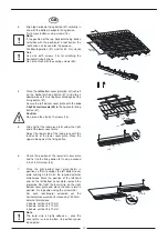
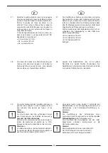
Replace the roof tiles on the uncovered area of the
roof and secure each of the tiles in the rows
adjoining the left and right sides of the solar-panel
space with tile clips (44). The tiles adjoining the right
side of the solar-panel space may have to be cut.
The tiles in the rows adjacent to the roof-integral
installation must have their hooks removed on the
side next to the cover plate. 
The tiles adjoining the top edge of the solar-panel
space generally have to be cut. The overlap over
the top cover plates depends on the angle of the
roof as follows:

  35˚ at least 120 mm

> 35˚ at least 100 mm
> 50˚ at least 80 mm

28.

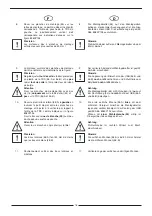
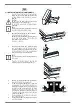
A tile clip (44) must be fitted to each tile in the two
rows adjoining the sides of the solar-panel
space. The tile clips fit around the tiles and
should be fitted on the side next to the cover
plate. 

29.

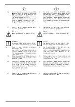
To the left or right (see Section 7) of and below
the solar-panel space, a vented roof tile (not
supplied) should be fitted so that the piping and
sensor cable can be passed through the roof. 


Note:

The vent hole in the vented tile must be large
enough for the connecting hoses 

together with

heat insulation

 and the sensor cable.

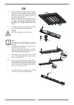
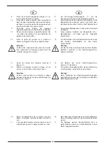
Remove the protective film from the butyl strip on
the lead skirts of the lower cover plate. Stick it
against de roof tiles.

Note:

The butyl strip is highly adhesive – once the lead
skirts are stuck in place, their position cannot be
adjusted.

GB

8980N472

8980N

500

32 31

44

30

8980N473

8980N474

Summary of Contents for PRO 2

Page 1: ... solaires Flachkollektoren Flat solar panels PRO 2 3 SUN 230 Notice de montage Intégration en toiture capteurs verticaux juxtaposés Indach Montageanleitung senkrecht nebeneinander Instructions for Roof integral Installation panels vertical side by side F D GB ...

Page 2: ... 8 Erforderliches Werkzeug und Material 7 1 9 Bauseits zu stellende Materialien 7 2 Normen und Richtlinien 9 3 Indach Montage 10 3 1 Allgemeine Begriffsbestimmungen für ID Montagewanne 10 4 Montageübersicht Unterkonstruktion 11 4 1 Abmessungen 12 4 2 Unterkonstruktion Indach Montage 14 5 Kollektormontageübersicht 28 6 Kollektor Montage 30 7 Kollektorverschaltung 36 7 1 Kollektoranschluss Set 36 7 ...

Page 3: ...rzwellige Sonnenlicht wird an dem selektiv beschichten Absorber in Wärme umgewandelt Von dort gelangt es über Wärmeleitung in das Absorberrohr und wird durch das Wärmeträgermedium in den Speicher geleitet Die Solar flüssigkeit erwärmt den Speicher mittels Sonnenenergie und kühlt dabei selbst ab Der abgekühlte Wärmeträger fließt anschließend wieder zurück in den Kollektor um neue Sonnenenergie zu t...

Page 4: ... min min 25 max max max 70 Type de montage vertical horizontal Einbauart senkrecht waagerecht Installation method vertical horizontal Capacité nominale Nenninhalt Nominal capacity env ca approx 1 55 l Rendement η0 Wirkungsgrad η0 Efficiency η0 env ca approx 77 Rendement η0 05 Wirkungsgrad η0 05 Efficiency η0 05 env ca approx 59 Déperdition thermique k1 Wärmeverlustbeiwert k1 Heat loss k1 env ca ap...

Page 5: ...sporteur doit en être avisé sans délai L intégralité du kit de montage à livrer doit être contrôlée avant installation à l aide de la liste accompagnant chaque kit Les emballages doivent être recyclés après l installation conformément à la législation locale Die Flachkollektoren sowie das Montagezubehör sind bei Transport und Lagerung sorgsam zu behandeln Sollte die Verpackung dennoch auf dem Lief...

Page 6: ...t die mindestens über eine Unterspannung Unterspann bahn verfügen müssen Die Wasser führung auf der Unterspannung sollte dabei in der Traufe Dachrinne enden Da die Dachlattung der Standard Dach konstruktion aus 50x30 mm Dachlatten besteht wurde das Montagesystem auf diese Abmessungen optimiert Unter Um ständen müssen die Montagesets den bauseitigen Bedingungen angepasst wer den Alle hierzu erforde...

Page 7: ...be Inbetriebnahme Befüllstation For installation Pencil Tape measure or folding rule 2 open ended spanners 17 19 mm 1 open ended spanner 13 14 mm Screwdrivers flat bladed and cross bladed sizes 2 and 3 6mm Allen key with T handle Cordless drill power driver with socket bit for sealing screw hexagonal head 8 mm Hammer Solar panel carrying handles EG 349 2 vented roof tile for passing the panel grou...

Page 8: ...er des charges et Cahier des clauses spéciales DTU 40 35 NF P34 205 1 mai 1997 Couverture en plaques nervurées issues de tôles d acier revêtues Partie 1 Cahier des clauses techniques et NF P34 205 2 Partie 2 Cahier des clauses spéciales DTU 40 36 NF P34 206 1 mai 1993 Couverture en plaques nervurées d aluminium prélaqué ou non Partie 1 Cahier des clauses techniques et NF P34 206 2 Partie 2 Cahier ...

Page 9: ...il 3 Zentrale Brauchwassererwärmungsanlagen DIN 4751 Teil 1 Wasserheizungsanlagen Offene und geschlossene physikalisch abgesicherte Wärmeerzeugungsanlagen bis 120 C Sicherheitstechnische Ausrüstung Teil 2 Wasserheizungsanlagen Geschlossene thermostatisch abgesicherte Wärmeerzeugungsanlagen mit Vorlauftemperaturen bis 120 C Sicherheitstechnische Ausrüstung Teil 3 Wasserheizungsanlagen Geschlossene ...

Page 10: ...oves It replaces the original roof covering and requires as a minimum a waterproof membrane which drains into the eaves roof gutter If necessary the attach ment at the eaves may need to be modified Fitting of the weatherproof baseplate system of the roof integral installation set can be carried out while the roof tiles are being fitted by the roofer This requires the fixing of additional fixing ba...

Page 11: ...e Seitliches Eindeckblech links Side cover plate left 34 B Tôle de recouvrement latérale droite Seitliches Eindeckblech rechts Side cover plate right 35 Planche de montage Montagebrett Fixing batten 36 A Tôle de recouvrement inférieure gauche Unteres Eindeckblech links Bottom cover plate left 36 B Tôle de recouvrement inférieure droite Unteres Eindeckblech rechts Bottom cover plate right 37 Latte ...

Page 12: ...ture Kolliliste Indach Montage Packing List Roof integral Installation Nombre de capteurs Anzahl Kollektoren Number of panels N colis Kolli Nr Pack no Désignation Bezeichnung Description N art Art Nr Art No 2 3 4 5 EG 331 Lot de base 2 capteurs Grundset 2 Kollektoren Basic set 2 panels 89807331 1 0 2 2 EG 332 Lot de 3 capteurs solaires 3 Kollektoren in Einwegverpackung Solar Panel Triple Pack 8980...

Page 13: ...x30x2 200 3 x Horizontal fixing batten 37 28x48x2000 30 x Screw 6x70 16 1 x Set of fixing plates and nails 41 consisting of 6 x Fixing plates 12 x Flat headed nails 8 x Taper section sealing strip 43 self adhesive 16 x Tile clip 44 4 x Small screw 45 1 x Instructions for Roof integral Installation 2 x Lead piece 46 89807360 1 1 1 1 EG 361 Kit d extension 1 capteur vertical pour intégration en toit...

Page 14: ...mm comme indiqué sur la figure suivante Prendre les mesures horizontales pour la tôle de recouvrement inférieure gauche TRS raccrocher la dernière tuile recouverte en bas à gauche mettre un repère sur les bons côtés au niveau des lattes de montage inférieures 37 puis enlever la tuile 110 mm vers la gauche à partir du repère extrémité de la TRS 2 Horizontales Ausmitteln der unteren Montagelatte 37 ...

Page 15: ...ith a perpendicular separation of 220 mm from the roof batten below it using the screws 16 as shown in the next illustration Ascertain the horizontal measurement for the bottom left cover plate as follows Replace the last covering roof tile bottom left and mark its right hand edge on the bottom horizontal fixing batten 37 then remove the tile again Measure 110 mm to the left from the position mark...

Page 16: ...veau que le tablier protecteur en plomb de la TRS La partie supérieure doit se placer contre la latte de montage 5 Den Bleizuschnitt 46 bis zur Hälfte unter den rechten Rand des UEBs schieben Die Unterkante soll bündig mit der Bleischürze des UEBs abschließen Die Oberkante an die Montagelatte anformen 6 Vérifier l orientation de la TRS gauche puis la fixer sur la latte de montage 37 à l aide d une...

Page 17: ...r side of the lead piece with the lead skirts of the lower cover plate Place the upper side against the fixing batten 6 Check the position of the lower left cover plate and fix it to the fixing batten 37 using a second 3 9 x 25 mm screw 45 7 Place the right bottom cover plate 36 B in position so that it overlaps the left bottom cover plate and align it to match the required external dimensions Mar...

Page 18: ...tylband noch nicht abziehen Attention Fixer les planches de montage 35 avec des vis 16 uniquement sur le lattis du toit 32 et pas sur la TRS 36 A et 36 B Achtung Die Montagebretter 35 mit Schrauben 16 nur auf der Dachlattung 32 und nicht auf dem UEB 36 A und 36 B befestigen 10 Poser le premier bac latéral 38 A à gauche en insérant le petit méplat entre les planches de montage et l ajuster à la ver...

Page 19: ... and 36 B or remove the protective film from the butyl strips Caution Using the screws 16 fix the perpendicular fixing battens 35 to the roof battens 32 only and not to the bottom cover plates 36 A and 36 B 10 Place the left side baseplate 38 A with the narrow valley between the perpendicular fixing battens and align vertically flush with the lip of the bottom cover plate as per Fig 8980P194 Secur...

Page 20: ...male Wanne 14 Insérer les tôles de recouvrement latérales TRL aux extrémités gauche 34 A et droite 34 B sous les pentes extérieures des bacs 14 Die seitlichen Eindeckbleche SEB links 34 A und rechts 34 B unter die äußeren Stege der Wannen schieben Précision Les arêtes intérieures de la TRL doivent se trouver sous les arêtes extérieures du bac Hinweis Die inneren Kantungen der SEB müssen unter der ...

Page 21: ... Note The last baseplate is a narrow one 14 Slide the left and right side cover plates 34 A and 34 B under the outer slopes of the baseplates 8980P198 Note The inner edges of the side cover plates must be underneath the outer edges of the baseplates 15 Fix the outer edges of the side cover plates 34 A and 34 B to the roof battens using the fixing plates 41 8980P199 Note The angled face of the fixi...

Page 22: ...Das Butylband besitzt eine hohe Klebkraft Blech kann nach Auflegen nicht mehr korrigiert werden 18 Glisser la pièce en plomb 46 à moitié sous le bord droit de la TRS La partie inférieure doit se positionner au même niveau que le tablier protecteur en plomb de la TRS La partie supérieure doit se placer contre la latte de montage 18 Den Bleizuschnitt 46 bis zur Hälfte unter den rechten Rand des OEBs...

Page 23: ...p is highly adhesive once the cover plate is in place its position cannot be adjusted 18 Slide half of the lead piece 46 under the right end of the upper cover plate Adjust the lower side of the lead piece with the lead skirts of the upper cover plate Place the upper side against the fixing batten 19 20 Check the position of the upper left cover plate and fix it to the fixing batten 37 using a sec...

Page 24: ...kten Sitz überprüfen und das Basisprofil 04 durch die vorgebohrten Löcher mit Dichtschrauben 39 am Montagebrett 37 befestigen Précision Le ruban de butyle est particulièrement adhésif le profilé ne peut plus être déplacée une fois posé Il est important que le ruban de butyl 42 e soit placé autour du trou entre le chapeau et le profilé de base Hinweis Das Butylband besitzt eine hohe Klebkraft Profi...

Page 25: ...and fix the mounting rail 04 through the pre drilled holes to the perpendicular fixing battens 37 using sealing screws 39 Note The butyl strip is highly adhesive once the mounting rail is in place its position cannot be adjusted It is important that the butyl strip 42 is between the ridge and the mounting rail at the point where the screw passes through 25 Fix the top mounting rails 04 in the same...

Page 26: ...a tuile elles doivent être montées sur l assemblage de tôles 28 Jeweils eine Kopfklammer 44 ist bei jedem Dachstein der beiden Reihen anzubringen Die Kopfklammern umklammern den Dachstein und sind zur Seite der Einblechung zu montieren 29 Une tuile chatière doit être installée à droite ou à gauche voir chapitre 7 sous le capteur solaire pour pouvoir faire passer les tuyaux et les câbles 29 Links o...

Page 27: ...m 28 A tile clip 44 must be fitted to each tile in the two rows adjoining the sides of the solar panel space The tile clips fit around the tiles and should be fitted on the side next to the cover plate 29 To the left or right see Section 7 of and below the solar panel space a vented roof tile not supplied should be fitted so that the piping and sensor cable can be passed through the roof Note The ...

Page 28: ...des capteurs solaires Kollektorfeld Anschluss Set Solar panel basis connection set 07 Kit de liaison hydraulique entre 2 capteurs Kollektor Verbindung Solar panel connection set 08 Vis universelle M8x14 Universalschraube M8x14 Universal bolt M8x14 09 Patte de serrage Klemmhalter Fixing bracket 10 Vis de fermeture Formschluss Schraube Interlock bolt 11 Raccord à bague de serrage Klemmringverschraub...

Page 29: ...29 ...

Page 30: ...rage 09 sur les extrémités du profilé de base 3 Die Nutsteine 05 mit der Kugelseite nach innen am linken Ende der Basisprofile 04 einclipsen und so positionieren dass die Klemmhalter 09 bündig an den Basisprofil Enden festgeschraubt werden können 4 Précision La cale coulisseau s enclipse par le haut Poser le premier capteur plan sur le profilé de base 04 les tenons de montage 14 4 Hinweis Der Nuts...

Page 31: ...tion them so that the fixing brackets 09 can be screwed down flush with the ends of the mounting rails Note The anchor blocks can be snapped into place from above 4 Place the first flat solar panel in place on the mounting rails 04 and mounting hooks 14 5 Remove the carrying handles from the first solar panel and fit them to the second panel 6 On the left side of the solar panel 01 snap two fixing...

Page 32: ...ektor an den ersten heranschieben Attention Veiller au bon alignement des raccords Guider avec précaution le deuxième capteur dans les raccords à bague de serrage Achtung Auf die Flucht der Anschlussstutzen achten Zweiten Kollektor vorsichtig in die Klemmringverschrau bungen einführen 14 Serrer les écrous des premiers raccords à bague 11 14 Die Muttern der ersten Klemmringverschrau bungen 11 festz...

Page 33: ... sure the connections on the two panels are aligned Slide the connections on the second solar panel into the clamping ring fitting carefully 14 Tighten the nuts on the first clamping ring fitting 11 15 Tighten the second and any additional clamping ring fittings in the same way Caution When tightening the clamping ring fittings use a second spanner to prevent the centre part of the fitting from tu...

Page 34: ... la deuxième et le cas échéant les autres liaisons de la même façon 18 Nach erfolgreicher Dichtigkeitsprüfung der Solaranlage werden die Kollektorverbindungen mit einer Wärmedämmung umgeben Die Schutzfolie der Wärmedämmung 12 abziehen und die Wärmedämmung um die erste hydraulische Verbindung legen Danach die Wärmedämmung wieder verkleben Die zweite und gegebenenfalls weitere Verbindungen in gleich...

Page 35: ...or leaks place the heat insulation sleeves 12 on the hydraulic connections remove the protective film from the self adhesive sleeve and stick it over the heat insulation sleeve Insulate the second and any remaining fittings in the same way GB 12 8980N423 ...

Page 36: ...torfeld Anschluss Sets zurückschieben Klemmringverschraubungen auf die Anschlussstutzen stecken und festschrauben Attention Veiller à bien maintenir les raccords à bague pendant la fixation pour ne pas endommager les tuyaux du capteur Achtung Beim Festziehen der Klemmringverschraubungen gegenhalten da sonst die Verrohrung des Kollektors beschädigt werden kann 2 La tubulure retour intégré du dernie...

Page 37: ...to the solar panel pipe connections and tighten Caution When tightening the clamping ring fittings use a second spanner to prevent the centre part of the fitting from turning as otherwise the solar panel pipes may be damaged 2 On the last panel of a panel group the integrated return pipe is connected to the panel s serpentine piping The return pipe link 50 is connected across the pipe connections ...

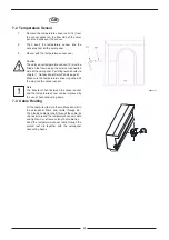
Page 38: ...chaltung Seite 36 Kollektor Temperaturfühler bis zum Ende der Tauchhülse einschieben Précision Il est possible d améliorer la transmission de chaleur entre le doigt de gant et la sonde de température en ajoutant une pâte conductrice Hinweis Der Wärmeübergang zwischen Tauchhülse und Temperaturfühler kann durch das Einbringen von Wärmeleitpaste verbessert werden 7 3 Guidage du câblage 7 3 Kabelführu...

Page 39: ... chapter 7 Connection of Solar Panels page 37 Make sure the temperature sensor is pushed all the way into the sensor socket Note The transfer of heat between the sensor socket and the temperature sensor can be improved by the use of heat conducting paste 7 3 Cable Routing Fit the cable tie clips into the multifunction slot in the solar panel frame and rotate through 90 Then feed a cable tie short ...

Page 40: ...viter que les capteurs et leurs raccordements soient endommagés par le gel et la corrosion il est indispensable d utiliser un fluide caloporteur de haute qualité mélange eau propylène glycol pour l installation solaire L utilisation d un mélange recommandé mélange TYFO L 40 60 constitue une bonne protection antigel jusqu à environ 24 C Um Frost und Korrosionsschäden an Kollektoren und Anschlüssen ...

Page 41: ...41 ...

Page 42: ...42 ...

Page 43: ...43 ...

Page 44: ...6 370 BP 30 57 rue de la Gare F 67580 MERTZWILLER Tél 33 03 88 80 27 00 Fax 33 03 88 80 27 99 www dedietrich com N IRC 347 555 559 RCS STRASBOURG Sous réserve de modifications techniques Technische Änderungen vorbehalten Subject to technical modifications ...

Reviews: