


USE R M ANU AL
TOUCHSCREEN 2.1
9
SEPTTEMBER 12, 2017
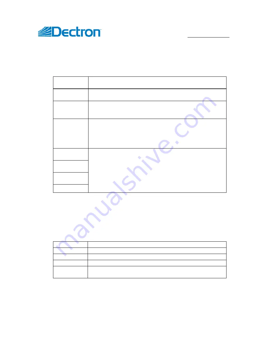
Status
To the right of the page you have the following
system’s status
indicators:
Comm
Green indicates successful SuperviseAir
®
board to
touch display communication. White otherwise
WebSentry
Green indicates successful WebSentry
®
communication.
White otherwise
Alarms
Red indicates that there are active alarms. Yellow
indicates that there are active alerts but no alarms. White
indicates that there are no alarms or alerts.
Blower
Green indicates that the main blower is running. Since all
other components of the system requires the blower to
run, white indicates that system is off but not powered off.
Indicator will be displayed only on Normal mode home
page
Dehum
Mode status. Green indicates that there is a mode
demand and white that there is no demand.
These indicators will be displayed only on Normal mode
home page; whether indicator is displayed or not is
dependent on system configuration (e.g. Pool Heat
indicator would not appear on the page, if system is
configured to not have pool heating
A/C
Space Heat
Pool Heat
Notes
button is also located on the home page below the status indicators. See
Leaving Notes
on page 18 for more information.
Menu
At the top of each page there are five menu buttons which grant quick access to
following features/pages from any page:
Home
Opens/returns to the home page
Logs
Access to
system’s logs
and log-related features
User
Access to user settings and commands
Advanced
Access to advanced settings and features
Help
Context sensitive help presenting information related to
the viewed page
While Home button function is simple and rather straight forward, other buttons
are multi-layered and more complex.


