


6.5.3c
6.5.3a
6.5.3b
Page 56
of
68
INDUSTRIAL PUMPS
www
.debem.com
Chapter 6 - ROUTINE MAINTENANCE
Translation of original instructions -
S
CUBIC-
S
BOXER
rev.
2021
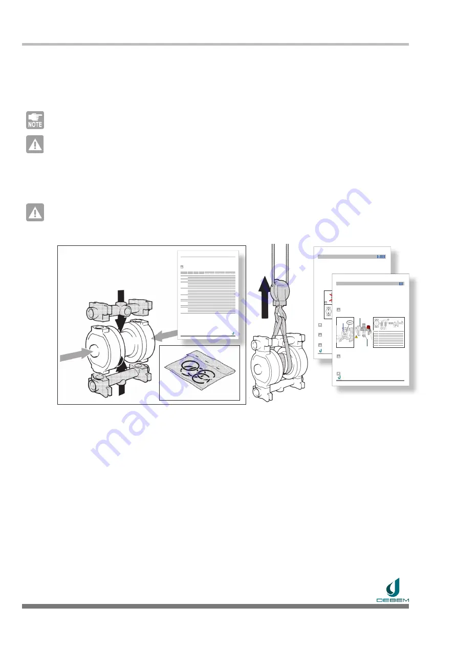
6.5.3
PUMP RE-ASSEMBLY
When the replacement of the pneumatic insert has been completed, the following steps are required to
reassemble the pump :
6.5.3a
Check the condition of the static pressure O-ring seals of the pump (that they are not dry, deformed or
crushed); if not, replace them with an Original Spare
Part (see Spare Parts Manual - BOXER and CUBIC)
.
NOTE
The PTFE static seal O-rings must be mandatorily replaced after every disassembly.
ATTENTION
:
Check the condition of the plates and disc springs, and if they are corroded or damaged, replace them with
Original Spare Parts
(see Spare Parts Manual - BOXER and CUBIC)
.
6.5.3b
Reassemble the pump in the reverse order to that described above and
tighten the fixing bolts progressively
and uniformly, observing the tightening torques indicated by the manufacturer
(see 6.3.2 TIGHTENING
TABLE page 48)
.
CAUTION
:
risk of stress corrosion cracking phenomena and sudden breakages.
Excessive tightening (especially on plastic pumps) can cause dangerous tensions on some components
and sudden breakages that cannot be attributed to construction defects.
6.5.3c
Carry out the repositioning and connections of the pump to the system and the pneumatic supply circuit,
working as described in
Section 4.4 and 4.5
.
Replacement of the pneumatic insert and reassembly of the pump is complete.
Page 48
of
68
INDUSTRIAL PUMPS
www
.debem.com
Chapter 6 - ROUTINE MAINTENANCE
Translation of original instructions -
S
CUBIC-
SBOXER
rev.
2021
6.3.2
TIGHTENING TORQUE TABLE
The following table shows the tightening torques referred to the construction components and their mate-
rials.
Tightening must be carried out in compliance with the tightening torques indicated by the Manufacturer
and expressed in Nm (Newton metre) referred to each model and construction material.
CAUTION: risk of stress corrosion cracking phenomena and sudden breakages.
Excessive tightening (especially on plastic pumps), can cause dangerous tensions on some components
and sudden breakages that cannot be attributed to construction defects.
PUMP
Material
CENTRAL
CORPO
PUMP
MANIFOLD
CAP
PLUG
OR-PTFE
OR-RUBBER
1 M
2 M
OR-PTFE
OR-RUBBER
SMIDGET
PP
--
4 Nm
--
15 Nm
--
SCUBIC
PP
--
4 Nm
4 Nm
15 Nm
8 Nm
ECTFE
--
4 Nm
4 Nm
15 Nm
8 Nm
SBOXER 7
PP
--
4 Nm
4 Nm
15 Nm
--
PVDF
--
4 Nm
4 Nm
15 Nm
--
SBOXER 15
PP
--
5 Nm
5 Nm
15 Nm
--
PVDF
--
5 Nm
5 Nm
15 Nm
--
AL
--
5 Nm
5 Nm
15 Nm
--
AISI
--
5 Nm
4 Nm
15 Nm
--
SMICRO
PP
--
4 Nm
6 Nm
4 Nm
17 Nm
--
PVDF
--
4 Nm
6 Nm
4 Nm
17 Nm
--
AL
--
4 Nm
8 Nm
17 Nm
--
AISI
--
4 Nm
10 Nm
17 Nm
20 Nm
SBOXER 50
PP
--
5 Nm
6 Nm
8 Nm
27 Nm
30 Nm
18 Nm
PVDF
--
5 Nm
6 Nm
8 Nm
27 Nm
30 Nm
18 Nm
AL
--
6 Nm
7 Nm
27 Nm
30 Nm
20 Nm
SMINI
AISI
--
4 Nm
5 Nm
27 Nm
30 Nm
20 Nm
SBOXER 81
PP
--
8 Nm
8 Nm
30 Nm
33 Nm
30 Nm
PVDF
--
8 Nm
8 Nm
30 Nm
33 Nm
30 Nm
AISI
--
8 Nm
8 Nm
30 Nm
33 Nm
30 Nm
SBOXER 90 AL
--
8 Nm
8 Nm
30 Nm
33 Nm
--
SBOXER
100
PP
--
8 Nm
10 Nm
8 Nm
33 Nm
33 Nm
PVDF
--
8 Nm
10 Nm
8 Nm
33 Nm
33 Nm
AL
--
5 Nm
7 Nm
33 Nm
33 Nm
AISI
--
6 Nm
10 Nm
33 Nm
33 Nm
4.3.1
OK
4.3.2
4.3.3
Page 31
of
68
INDUSTRIAL PUMPS
www
.debem.com
Chapter 4 - Transport and Positioning
Translation of original instructions -
S
CUBIC- S
BOXER
rev
. 2021
4.3 POSITIONING AND INSTALLATION
Installation operations are reserved for qualified and authorised Installation Technicians, equipped with suit
-
able Personal Protective Equipment (PPE), who are acquainted and comply with the contents of this Man
-
ual. Since an endless variety of products and chemical compositions exists, the user is presumed to have
the best knowledge of their compatibility and reaction with the pump’s construction materials. Before using
and installing the pump, all necessary checks and tests must be performed with great care to avoid even the
slightest risk, an event that the Manufacturer cannot foresee and for which he cannot be held responsible.
General installation requirements
• Adequate space to allow future maintenance;
• Installation of the pump with horizontal axis;
• Mounting on rigid supports (ceiling or floor) with flatness (0.1 mm);
• With negative head for fluids with Max density up to 5,000 Cps at 20°C and a Max specific weight of 1.4 Kg/l;
• Installations with positive head for fluids with Max density up to 20,000 Cps at 20°C;
• Positioning near the point of collection (max 10 times the suction diameter);
• Suction inlet away from vortices;
• Earthing the pump for installations in a potentially explosive environment;
• Pneumatic circuit supply with dried, unlubricated air;
• Installation of shut-off valve, 3-way valve and non-return valve on the air supply.
4.3.1
Position the pump with the axis horizontal at the place of installation, as close as possible to the point of
collection, aligning it with the suction and delivery ducts.
NOTE
The product delivery manifold must always be positioned in the upper area;
the arrows on the pump
casing must always be facing up
.
4.3.2
Provide for the tightening on rigid supports (to ceiling or floor with suitable flatness 0.1 mm) on feet with
appropriate washers and bolts. If necessary, provide suitable anti-vibration feet
(DEBEM catalogue)
.
CAUTION: danger of explosion
ATEX M2 pumps must be installed in a low-impact risk environment.
4.3.3
If the pump is made of conductive material (CONDUCT design), and suitable for pumping permissible
flammable fluids, a suitable earthing cable must be installed on each pump body;
danger of explosion
and/or fire due to electrostatic currents.
CAUTION: danger of explosion
The pump must always be earthed, independently of other parts connected to it. Failure to earth or incor
-
rect earthing will invalidate the safety and explosion protection requirements.
Pump positioning is thus completed.
4.4.1
4.4.2
9
4 5 6 7 8
1 2 3
4.4.3
4.4.4
Page 35
of
68
INDUSTRIAL PUMPS
www
.debem.com
Chapter 4 - Transport and Positioning
Translation of original instructions - SCUBIC - S
BOXER
rev
. 2021
ONLY
Air Filter
NO
OIL
ONLY
for glycol
Min 2 bar
Max 8 bar
4.4 PNEUMATIC CONNECTION
Connection operations to the pneumatic system are reserved for qualified Installation Technicians and
,
equipped with suitable Personal Protection Equipment, who know and comply with the contents of this
Manual. After completing the installation operations, the pump can be connected to the pneumatic supply
circuit as follows:
Pneumatic system requirements
•
Supply with non-lubricated, dried air, with suitable pressure (Min 2 bar - Max 8 bar);
• Use of pneumatic components with air flow rates suitable for the pneumatic circuit of the pump;
•
Glycol adder for installations with strong delivery heads and/or back-pressures;
• Installation of a shut-off valve, 3-way valve and check valve on the air supply;
• Installation of air discharge pipe (with collection) outside of harsh and potentially explosive atmos
-
pheres and for pumping flammable or toxic fluids.
4.4.1
Remove the adhesive from the pump air connections.
CAUTION: danger of pump blocking.
The pneumatic supply of the SCUBIC and
SBOXER
pumps must be carried out with UNLUBRICATED, FIL
-
TERED, AND DRY compressed air with a pressure of not less than 2 bar and not more than 8 bar.
4.4.2
Screw two fittings of suitable diameter onto the pneumatic circuit connections of the pump, for the supply
connection to the piloting valve.
POS.
COMPONENT
1
Air pump
2
2/3-way valve or Oscillator
3
Pressure gauge
4
3-way valve - air discharge (START - STOP)
5
Check valve
6
Soft start valve
7
Filter/Regulator (20µ - micron)
8
3-way valve - interlockable (EMERGENCY)
9
Pressure Relief Valve
4.4.3
Set up a pneumatic oscillator, or a 2/3-way pneumatic valve (for remote control from PLC) and a valve
(START - STOP with air exhaust)
, according to the diagram in the figure.
To check the actual pressure of the supply air, a pressure gauge must be installed on the compressed air
line near the pump itself and the value checked when the pump is running.
CAUTION:
danger of fluid entering the compressed air circuit and being discharged into the environment.
It is forbidden to install the pump without a 3-way valve (START - STOP)
and/or a non-return valve to prevent
the pumped fluid from entering the pneumatic circuit in the event of a rupture of the diaphragms.
Even in battery installations, the check valve must always be installed on each pump.
4.4.4
Install a 3-way valve for the emergency stop control (disconnecting switch with interlock) in a protected and
easily accessible position, upstream of the pneumatic circuit supplying the pump.
4.4.5
Installations where operation with many Start / Stop cycles is expected (with high delivery heads and / or
with strong back-pressures) require the installation of a pneumatic soft start valve to protect the product
diaphragms.
NOTE
The installation of the soft start pneumatic valve, in addition to allowing a more uniform and fluid pump
-
ing of the product during the start-up phase, allows the protection of the diaphragms and preserves the
operating life of the pump.