115.6031.0
- 32 -
3.10 Shutdown for Non-Extended Periods
This procedure is for those instances where gas feed will be intermittent and the Vaporizer is maintained at the
operating temperature. If the Vaporizer heater is to be turned off, refer to paragraph 3.11.
WARNING
Do not close any valves on the liquid gas piping or the source containers.
Doing so will trap liquefied gas causing the safety rupture discs
and pressure relief valve to open, venting gas
1) Turn off the Gas Dispenser(s).
2) Maintain the Vaporizer in a “standby” mode with all power maintained on the Vaporizer.
3.11 Shutdown for Servicing or Extended Periods
1) Turn on the Gas Dispenser(s).
2) Nitrogen Trichloride: The presence of nitrogen trichloride (NCl
3
) in liquid Chlorine is the suspected cause of
explosions that have occurred, although infrequently, in Chlorine systems. Nitrogen trichloride may be formed
in minute quantities during the production of Chlorine by the reaction of Chlorine with various nitrogen
containing compounds. Evaporation of Chlorine in a closed container (such as a vaporizer) may concentrate
this compound because NCl
3
has a higher boiling point than Chlorine. If sufficiently concentrated, NCl
3
can
decompose spontaneously in an explosive fashion. For this reason, it is critical to never allow liquid Chlorine to
fully evaporate in the Vaporizer. Prior to emptying the liquid from the Vaporizer for maintenance it should be
purged with liquid Chlorine known to have low levels of NCl
3
. Refer to The Chlorine Institute pamphlets 21
and 152.
3) Close the liquid supply valve(s).
4) Continue to operate the Gas Dispenser(s) until the gas pressure gauge on the Vaporizer falls to zero, indicating
that all liquid and gaseous chemical has been evacuated from all piping and assemblies including the vaporizing
chamber. Turn off the gas dispenser(s) and observe the system gas pressure gauge(s). If the pressure rises above
"0", restart the gas dispensers until the gas is evacuated.
5) Open all external switches in the power supply line to the control circuit connection box; open the circuit breaker
in the power supply line to the heating elements of the electric immersion heater.
6) Close the throttling valve of the water supply piping assembly (or the shut-off valve in the water supply line) and
open the drain valve of this assembly to drain the water chamber.
Before starting up the Vaporizer System after servicing, refer to the Start-Up procedure at the beginning of
this Section.
Summary of Contents for Capital Controls 71V3B Series
Page 1: ... 1 115 6031 0 Instruction Manual Series 71V3B Electrically Heated Vaporizer CAPITAL CONTROLS ...
Page 9: ... 9 115 6031 0 Figure 1 Sectional Diagram ...
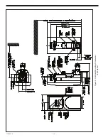
Page 17: ... 17 115 6031 0 Figure 4 Outline Mounting Dimensions 12 kW 15 kW Heaters ...
Page 18: ...115 6031 0 18 Figure 5 Outline Mounting Dimensions 18 kW Heater ...

