- 13 - 115.6031.0
1.3.3.3 Vent Blow-Off Valve
The vent blow-off valve (see Figure 2) serves as a convenient means for venting the vaporizing
chamber to atmosphere to permit air purging of all gas vapors from this chamber prior to removing
it for routine cleaning and inspection.
While De Nora Water Technologies recommends that this option be installed, the vent blow-off
valve is not supplied by De Nora Water Technologies.
The valve must be capable of being locked in the closed position to prevent accidental opening
with an operating or pressurized system
1.3.3.4 Cathodic Protection
The water chamber is equipped with four magnesium rods to provide cathodic protection of all
metallic surfaces in contact with the water. The anodic action of the rods reduces the galvanic
corrosion of these surfaces, which is generally accelerated in the presence of heated water. These
rods extend downward into the water chamber through individual mounting connections in
the chamber cover and are held vertically in position by companion support guides affixed to the
outer wall of the vaporizing chamber. The rods are the active components of the protection circuit,
which operates on the electrochemical principle of the flow of current between two dissimilar
metals immersed in a conductive fluid. The mounting connections and support guides are
electrically insulated. The current which flows from the more active magnesium (anode) to the less
active metallic surfaces (cathode) is controlled by a constant-current cathodic protection circuit.
This circuit is designed to regulate the protective current at approximately 50mA. In the event that
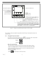
the red indicator on the temperature control panel comes on at start-up, it is an indication that
there is a problem with the conductivity of the water and that the 50mA protective current cannot
be maintained by the cathodic protection circuitry. Should this occur, the conductivity of the water
must then be increased by adding Sodium Sulfate or Magnesium Sulfate (Epsom Salts) through the
electrolyte addition port until the red indicator light is extinguished.
DO NOT USE SODIUM CHLORIDE (TABLE SALT) AS SEVERE CORROSION AND LIMITED ANODE
LIFE
WILL
RESULT.
Should the red indicator become active after a period of operation, it may
indicate that the magnesium rods have been consumed. Check the condition of the magnesium
rods and replace them if necessary.
1.3.4 Optional Accessory
1.3.4.1 Water Level Control
An optional water level control switch, operating in conjunction with a normally closed solenoid
valve installed in the water supply piping, can be furnished to sense and automatically control
the level of the water in the water chamber at the optimum desirable operating level. This
pressure operated switch, which provides a contact closure on falling water level and a contact
opening on rising water level when the pressure setting is reached, acts via the coil of the
solenoid valve to start and stop water flow to the chamber to maintain the level of water at the
chamber operating level.
As an alternative to the above, De Nora Water Technologies offers a Purge Meter (P/N 806H022U01)
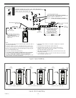
for trickle-filling of the Vaporizer. Installation of this Purge Meter assembly and the associated
piping is shown in the Recommended Piping Arrangements inset of Figure 3. When using the
Purge Meter filling method, the Purge Meter should be set to establish a small trickle flow at
the drain for proper operation.
This method MUST be used when the Vaporizer is being
used to vaporize Sulfur Dioxide.
Summary of Contents for Capital Controls 71V3B Series
Page 1: ... 1 115 6031 0 Instruction Manual Series 71V3B Electrically Heated Vaporizer CAPITAL CONTROLS ...
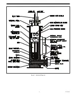
Page 9: ... 9 115 6031 0 Figure 1 Sectional Diagram ...
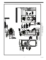
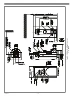
Page 17: ... 17 115 6031 0 Figure 4 Outline Mounting Dimensions 12 kW 15 kW Heaters ...
Page 18: ...115 6031 0 18 Figure 5 Outline Mounting Dimensions 18 kW Heater ...


