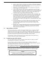
- 27 - 115.6031.0
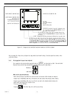
3.6.2 Changing the Temperature Units
The following steps describe the procedure for changing the displayed temperature units either from
°F to °C or °C to °F. Temperature control will be suspended while performing this change.
3.6.3 Description of Menu Structure
The programming for the controller is broken down into three menus (Operation, Regulation, and Initial
Setting). Upon normal operation, control will be in the Operation Menu.
NOTE: When changing the parameter, the display will flicker.
ENTER must be pressed to save the change.
3.6.4 Operation Menu
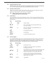
Pressing the INDEX key will cycle through the below menu items. The parameter will be displayed in the top
display, while its value will be displayed in the bottom display. The UP and DOWN arrows change the values
of the parameters.
Menu
Default Settings
Activates
outputs.
170
Alarm 1 High Set Point must be changed after Start-up
procedure
is
complete
140
Alarm 2 Low Set Point must be changed after Start-up
procedure
is
complete.
Set
front
panel
security
lock.
Lock
all
settings.
Lock all setting except the set point.
3.6.5 Initial Setting Menu
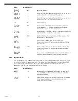
Press and hold the ENTER key for at least 3 seconds while at the Home Display in order to access the Initial
Setting Menu. Pressing the INDEX key will cycle through the below menu items. The parameter will be
displayed in the top disply, while its value will be displayed in the bottom display. The UP and DOWN arrows
change the values of the parameters. The ENTER key must be pressed after any changes.
Menu
Default Settings
Thermocouple
T
type
2
F
Temperature Units. This parameter is only available for
thermocouple
or
RTD
units.
210
Scale Height Limit. Sets the upper limit of the temperature range.
or
If the process temperature exceeds this setting, the display
205
will flash an error code. (210 for Cl
2
and NH
3
, 205 for SO
2
)
Scale Low Limit. Sets the lower limit of the temperature
35
range. If the process temperature exceeds this setting, the
display
will
flash
an
error
code.
on-off
Control Mode
Summary of Contents for Capital Controls 71V3B Series
Page 1: ... 1 115 6031 0 Instruction Manual Series 71V3B Electrically Heated Vaporizer CAPITAL CONTROLS ...
Page 9: ... 9 115 6031 0 Figure 1 Sectional Diagram ...
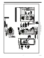
Page 17: ... 17 115 6031 0 Figure 4 Outline Mounting Dimensions 12 kW 15 kW Heaters ...
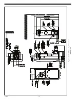
Page 18: ...115 6031 0 18 Figure 5 Outline Mounting Dimensions 18 kW Heater ...

