- 29 - 115.6031.0
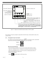
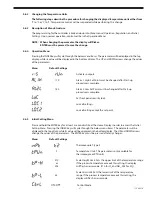
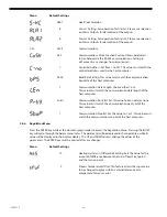
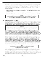
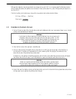
3.6.7 Controller Operation
During operation, Normal Water Temperature is indicated when ALM1 LED on the controller is not lit and the
and the ALM2 LED on the controller is lit.
A High Water Temperature Alarm is indicated when the ALM1 LED is lit.
A Low Water Temperature Alarm is indicated when the ALM2 LED is not lit.
3.7
Placing in Operation
1) After the system has been tested using gas, connect the liquid chemical to the manifold piping.
2) Close the outlet valve on the vaporizer and the by-pass valve around the pressure reducing and shut-off valve.
3) If the vaporizer is at operating temperature, begin to add liquid chemical. Slowly open the feed valve for the
liquid chemical supply and immediately close it. Check the valve connections for leaks. If no leaks appear, open
the valve one full turn. Allow 5-10 minutes for the system to stabilize, then open the vaporizer's outlet valve.
4) Turn on the gas dispenser and manually set the gas feed rate valve to approximately 25% of maximum
operating capacity. Allow ample time for the vaporizer gas temperature to stabilize. Read the gas pressure and
temperature gauges to verify the superheat requirements as described in Section 3.8. If the superheat value falls
below the required value, increase the water temperature controller setting to maintain the proper superheat.
5) If the gas is superheated to the required temperature and pressure parameters, increase the gas feed rates to
50%, then 75%, and finally 100% of total capacity, waiting after each feed rate change to confirm that the
vaporizer is maintaining the proper superheat and the heating is cycling on and off.
6) Contact De Nora Water Technologies if the water temperature controller must be set above 165°F for Chlorine to
provide the minimum superheat requirement the first time the vaporizer is placed in operation. This is indicative
that the following conditions could exist:
•
The chemical pressure is too high. This could be caused by:
1) padding pressure (if used) being too high
2) chemical source located above the Vaporizer
3) chemical container could be located in direct sunlight or direct heat
•
The rating of the immersion heater is incorrect.
•
The temperature controller is faulty.
7) Once it is determined that the vaporizer is operating properly at maximum capacity, reduce the gas feed rate
to the normal requirements of the gas feed system. DO NOT reduce the temperature control set-point value.
The vaporizer can operate at temperatures above the required superheat at lower feed rates, thus allowing rate
changes up to maximum without having to change the controller setpoint.
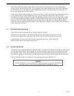
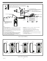
Figure 11 - Controller Operation Label
HIGH WATER TEMP ALM1
ALM1
NORMAL WATER TEMP
ALM2
LOW WATER TEMP ALM2
Summary of Contents for Capital Controls 71V3B Series
Page 1: ... 1 115 6031 0 Instruction Manual Series 71V3B Electrically Heated Vaporizer CAPITAL CONTROLS ...
Page 9: ... 9 115 6031 0 Figure 1 Sectional Diagram ...
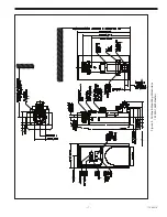
Page 17: ... 17 115 6031 0 Figure 4 Outline Mounting Dimensions 12 kW 15 kW Heaters ...
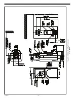
Page 18: ...115 6031 0 18 Figure 5 Outline Mounting Dimensions 18 kW Heater ...

