270
271
Assembly Guide
270
271
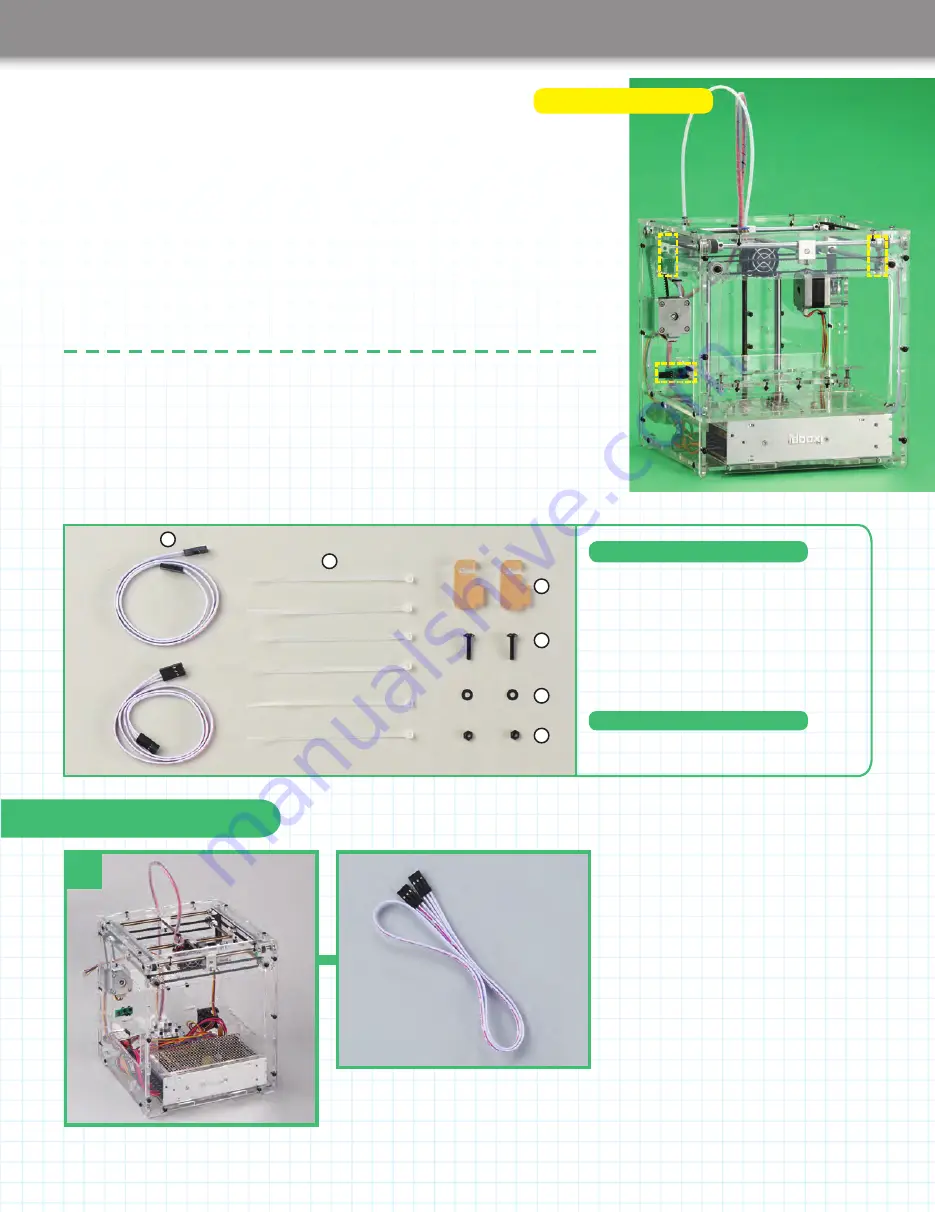
Stage 43: Connect the
X-, Y- and Z-axis limit
switches to the driver board
When you insert the pins on the limit
switches into the connectors on the
ends of the cables, be sure to do this
carefully and not bend the pins. Make
sure you get the connectors in the
correct positions on the driver board.
Secure the limit switch cables using
ties supplied with this stage and others
attached to the housing in Stage 39. After
you have plugged the thermistor cable into
the driver board, tidy up the cables in the
bottom of the housing.
1:
Limit switch cables x 2
2:
Cable ties x 6
3:
Brackets x 2
4:
M3 truss head screws (14mm) x 2
5:
M3 washers x 2
6:
M3 nuts x 2
Stage 43 Components
In this stage, you connect up the three limit switches to the driver board using the two
cables supplied with this stage and the one supplied with Stage 3. You will also plug in
the thermistor cable to the driver board and tidy up the cables.
Tools you will need
Scissors
Parts to have ready
1
Get ready the printer housing and the limit
switch cable that was supplied with Stage 3.
Stage 43 Assembly Area
1
2
3
4
5
6


