background image

®

Getting Started

Section 1

ZonePro

Summary of Contents for Zone Pro 640

Page 1: ...User Manual 640 641 ...

Page 2: ...ervice personnel or equivalent This Equipment is intended for rack mount use only SAFETY INSTRUCTIONS NOTICE FOR CUSTOMERS IF YOUR UNIT IS EQUIPPED WITH A POWER CORD WARNING THIS APPLIANCE MUST BE EARTHED CONNECT ONLY TO A MAINS SOCKET OUTLET WITH PROTECTIVE EARTHING CONNECTION The cores in the mains lead are coloured in accordance with the following code GREEN andYELLOW Earth BLUE Neutral BROWN L...

Page 3: ...that may cause undesired operation Operation of this unit within significant electromagnetic fields should be avoided use only shielded interconnecting cables DECLARATION OF CONFORMITY Manufacturer s Name dbx Professional Products Manufacturer s Address 8760 S Sandy Parkway Sandy Utah 84070 USA declares that the product Product name dbx 640 and dbx 641 Note Product name may be suffixed by the lett...

Page 4: ...guration Wizard 10 3 3 Scene Wizard 14 3 4 Schedule Wizard 15 Section 4 Detailed Parameters 4 1 Input 18 4 2 Input EQ 18 4 3 Automatic Gain Control AGC 19 4 4 Notch Filters 20 4 5 Compressor 21 4 6 Noise Gate 23 4 7 De Esser 24 4 8 Advanced Feedback Suppression AFS 25 4 9 Router 27 4 10 Auto Warmth 28 4 11 Band Pass Filter Crossover 29 4 12 Output PEQ 30 4 13 Output Dynamics 30 4 14 Delay 32 3 15 ...

Page 5: ...INTRO CUSTOMER SERVICE INFO Defining the ZonePro WARRANTY INFO INTRODUCTION 640 641 ...

Page 6: ...e that includes system setup and configuration This manual will be your guide to understanding the full functionality of the powerful ZonePro units By combining the different components the configuration possibilities are limitless After you have become familiar with the unit we encourage you to experiment and find the most effective and efficient way to run your system by utilizing the powerful p...

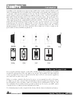
Page 7: ...arallel wiring to the unit With a maximum length of 1 000 ft the Zone Controllers offer a simple way to create a simple yet ele gant solution to many installation applications If you require technical support contact dbx Customer Service Be prepared to accurately describe the problem Know the serial number of your unit this is printed on a sticker attached to the top panel If you have not already ...

Page 8: ... within the U S to be free from defects in materials and workmanship under normal use and service 3 dbx liability under this warranty is limited to repairing or at our discretion replacing defec tive materials that show evidence of defect provided the product is returned to dbx WITH RETURN AUTHORIZATION from the factory where all parts and labor will be covered up to a period of two years A Return...

Page 9: ... Getting Started Section 1 ZonePro ...

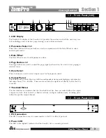
Page 10: ...rs 4 Outputs Channels 1 4 The output section of the ZonePro offers four electronically balanced Euroblock connectors 5 Input Link Buss RJ 45 connector type The ZonePro offers an input buss that duplicates inputs from one unit to the next for applica tions requiring more than four output zones 6 Input Source Channels 1 4 The input section of the ZonePro offers four mono summing unbalanced RCA conne...

Page 11: ...or front panel control 6 Output Meters The ZonePro 640 provides the user with four independent six segment Lightpipe output meters that range from 30 to 20 dBu These meters monitor the signal level directly before the D A converter 7 Threshold Meters The threshold meters indicate that the threshold level has been exceeded within the output Compressor Auto Gain Control or Limiter sections and gain ...

Page 12: ...nce all of the connections have been made and the unit is powered up you can navigate through the entire signal path of the ZonePro from the included GUI Minimum System Requirements 1 GHz processor Windows 2000 or XP 128 meg RAM Recommended screen resolution 1024 x 768 pixels or higher Installation Install the ZonePro GUI software from either the dbx website at www dbxpro com or from the included ...

Page 13: ...SOFTWARE OPERATION Section 2 ZonePro ...

Page 14: ...for exact duplication of a system in a single file download There are three different views within the ZonePro Designer GUI Venue view Program screen and Module view Venue view From the Venue View you can add or delete devices and con figure your network including selecting your COM port Double clicking on a unit icon in the Venue view takes you to the Program screen Program screen provides you wi...

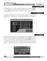
Page 15: ...rd sec tion 3 1 To edit a processing module double click on that module Adjust the module to taste make sure that the module is engaged This is usually indicated by the module ON button in the upper left corner of the parameter section Although process editing is done in real time the changes can either be discarded or accepted by selecting the OK or CANCEL button The following screen shot shows t...

Page 16: ...e GUI or it can be set using the Edit tab on the Menu bar and selecting time The input and output level meters can be turned off by clicking on the Meter button Turning the meters off will help speed the communication and processing of slower computer systems The ZonePro Designer GUI defaults with the meters turned on The device file provides a way to store off the entire ZonePro unit to a compute...

Page 17: ...SYSTEM SETUP Setup Section 3 ZonePro ...

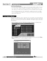
Page 18: ... one scene is desired save this as the Default Scene Step 4 Scene Wizard If multiple scenes are desired with routing or zone controller assign ment changes use the Scene Wizard to make those changes Repeat Steps 2 and 3 Step 5 Schedule Wizard If multiple scenes are to be loaded using the Schedule function setup the Schedule using the Schedule Wizard for each scene change Make sure the clock is cor...

Page 19: ...d selected insert modules click on the Next Page button and the display will appear as follows 3 2 2 Output Setup This page is the Output Setup Page and allows naming of the outputs zone configuration and selection of the Dynamics DSP module The outputs can be configured as mono or stereo either with or without a subwoofer Once you have performed all of your output setup modifications click on the...

Page 20: ...f scene selection A ZC FIRE can only be assigned to ID 2 Select whether the ZC FIRE should be activated when taken high or low Select to either Mute all outputs or select the desired scene to be loaded Volume A ZC 1 ZC 2 ZC 6 or ZC 8 can be used to adjust volume Select the desired ZC type and make sure it has the correct ID number Set the maximum and minimum values for this zone controller As a de...

Page 21: ... position choose the zones or groups of zones that are to be paged Once you have performed all your zone controller configurations click NEXT to move to the Routing Configuration 3 2 4 Routing Setup The Routing Setup Page allows selection of the main Source the Priority override source the Page source and the output level for each of the output zones If Zone Controllers are used for either source ...

Page 22: ...s accomplished by selecting finish You will now be returned to the normal editing mode of the ZonePro GUI The Scene Wizard function is used to setup the various scenes that may be required within the installation The Scene Wizard menu offers a single page window that provides a menu based decision tree to speed setup This sub section will walk you through the options of the Scene Wizard function F...

Page 23: ...etting up the Schedule Wizard From the Unit view of the setup the display will appear something like this Select the Wizard pull down from the menu bar and then select the option labeled Scheduler Wizard Once selected a window will appear as follows At this point you can create a schedule for each day of the week by recalling scenes at any time with up to 1 minute resolution Up to 24 scenes can be...

Page 24: ...System Setup 16 Section 3 ZonePro ZonePro User Manual ...

Page 25: ...DETAILED PARAMETERS Detailed Parameters Section 4 ZonePro ...

Page 26: ...o 20dB Adjusts the input level HP Frequency Off 14 96Hz to 118 85Hz Mic Inputs Only Adjusts the input High Pass cutoff frequency The ZonePro units offer Pre crossover parametric sections on each input and may be config ured as a single or linkable 2 band RCA inputs only or 4 Band PEQ Mic inputs only EQ On Off Turns the PEQ on and off Type Low Shelf HighShelf Low High Shelf and Bell The Type select...

Page 27: ...e selected Target by slowly adjusting the gain The maximum gain that can be applied to the signal is selected by the Gain parameter When the input signal falls below the Threshold the AGC releases the gain and returns to unity This prevents the AGC from adding gain when there is no signal present and raising the system noise floor High level peak signals are reduced by a fast limiter to prevent di...

Page 28: ...will increase gain Release 30 0 to 1 dB Second This adjusts how fast the AGC will reduce gain AGC Limiter Threshold 40 to 20dBu The AGC is designed to add or remove gain slowly to maintain an average signal level Because of its slow nature a fast Limiter has been added to protect speakers from sudden tran sients The Limiter threshold can be set from the top of the AGC Window up to 20dBu AGC Limite...

Page 29: ... Sets the level of the selected notch filter Set to 6dB to help find unwanted feedback then set to 3dB to 36dB to remove The ZonePro also offers a dedicated compression module The Compressor is the perfect tool for tightening uneven signal sources such as vocals and guitars The parameters for the Compressor are as follows 4 5 Compressor Insert and DYN Module Detailed Parameters Section 4 ZonePro Z...

Page 30: ...ral com pression is achieved when most of the signal content remains just below the threshold and only the peaks cross the threshold Ratio 1 0 to Inf 1 Ratio is the amount the unit reduces the signal level of the sound that is above the threshold A 2 1 ratio means that if the incoming signal is 2dB over the threshold the unit will compress the signal and outputs a signal that only goes 1dB over th...

Page 31: ...e the ZonePro remains in compression after the signal has dropped below the threshold A longer hold time is useful in smoothing out the sound when compressing several fast peaks that are fairly close together in time The hold control is not active while in auto mode Release 360 dB Sec to 5 dB Sec Release is how fast the ZonePro comes out of compression The release is in dB per second For example i...

Page 32: ...ain so that it becomes 4dB below the threshold Attack 0 1 to 200 m Sec As the signal reaches the threshold area the Attack control sets the speed at which the gate opens Use very fast attack times to catch the fronts of transient signals Hold 0 to 500 m Sec The Hold control sets the amount of time the gate is held open after the signal passes below the threshold point Release 360 to 5 dB Release s...

Page 33: ...icrophone is reproduced by an amplification and is repeatedly picked up in phase The AFS module of the ZonePro allows the user to optimize the elimination of feedback With the AFS algorithm active the ZonePro removes only the feedback frequencies without affecting the remaining audio spectrum AFS On Off Turns the AFS module on and off If AFS is Off the filters are bypassed and the algorithm is hal...

Page 34: ...der notch filters at these lower frequencies below 700 Hz Total Number of Filters 1 12 This parameter selects the number of filters being used Number Fixed 0 12 This parameter sets the number of Fixed AFS filters This also sets the number of Live filters as the Total number of filters number of Fixed Filters number of Live Filters Live Filter Lift On Off This parameter turns the Live Filter Lift o...

Page 35: ...rce signal Page Level Inf to 20dB Adjusts the output level of the selected Paging input signal Master Level Inf to 20dB This parameter adjusts the output level of of the Zone Master mute When selected the the signal will be muted for the Zone The Router contains two Ducker modules for Priority and Page sources The Priority Ducker attenuates the primary source and adds the Priority source The Prior...

Page 36: ...ated by the Ducker Hold 0 1 to 20 2 m Sec Hold time is the length of time before the Ducker releases Release 0 0 to 10 0 dB Sec Release is how quickly the attenuated signal returns to its nominal level The ZonePro 640 and 640 offer the AutoWarmth module on each output AutoWarmth is a patent pending process that compensates for naturally occurring bass frequency loss for low level signals The Fletc...

Page 37: ... gradually increase Be careful when using AutoWarmth followed by an AGC The AGC can add gain when below the AutoWarmth threshold resulting in overcompensated Bass Amount 0 25 1 to 4 00 1 The amount controls how much Bass is added A setting of 1 00 1 compensates the signal as described by the Fletcher Munson Equal Loudness curves Higher settings greater that 1 00 causes more bass Lower setting resu...

Page 38: ...Low Shelf Selects the frequency of the low pass shelf parametric EQ Q 1 6 0 105 to 16 0 Q is adjustable from 0 105 to 16 000 Slope Type High and or Low Shelf Selected 3 12dB Octave Sets the slope of the High and or low shelf parametric EQ Level 1 6 12 to 12 dB Sets the overall level of the selected parametric EQ frequency The ZonePro units offer a dedicated output dynamics module which includes Co...

Page 39: ...ontent remains just below the thresh old and only the peaks cross the threshold Auto On Off When auto is turned on the ZonePro will continuously set the attack hold release controls itself Attack 01 to 200 m Sec per band or global This is the speed at which the limiter starts to limit the signal once it has crossed the threshold Hold 0 to 500 m Sec per band or global Hold is the time the limiter s...

Page 40: ...Predictive Limiting Its function is to monitor the input signal and intelligently predict the amount of gain reduction needed to keep the output signal below the ceiling set by the Instantaneous Transient Clamp Overshoot 1 6 This parameter sets the amount of overshoot for the Instantaneous Transient Clamp The parameters for the delay are as follows and are user adjustable Delay On Off Turns the de...

Page 41: ...APPLICATION GUIDE Section 5 ZonePro ...

Page 42: ...Application Guide 34 SECTION 5 ZonePro ZonePro User Manual 5 1 Retail Install ...

Page 43: ...m the front panel of the ZonePro 640 3 The Zone Controllers are wired with CAT5 cable in series with the ZC 3 Source Selection as ID 1 and ZC 1 Volume as ID 2 and are placed next to the cash register 4 EQ Feedback Suppression and De Essing are used on the phone page input to help improve intelligibility and reduce unwanted feedback in the system 5 The Bandpass Filters are used to reduce the out of...

Page 44: ...Application Guide 36 SECTION 5 ZonePro ZonePro User Manual 5 2 Restaurant Bar Install ...

Page 45: ...cenes have been created that accommodate changes in the venue such as a volume boost in the bar for happy hour as well as the regular volume boost in the restaurant for the lunch time rush and the dinner crowd 6 The ZC 3 in the restaurant is used to change between scenes as needed 7 The Schedule function has been used to load the Rest Boost scene automatically at the begin ning of the lunch and di...

Page 46: ...Application Guide ZonePro User Manual 38 Section 5 ZonePro 5 3 Health Club Install ...

Page 47: ... Whenever the TV is on its audio is routed to the treadmill room and it can also be selected in the weight room 6 The locker rooms always have as their primary source the Satellite Music and receive paging from the front desk 7 Since we do not need the Aerobics Mic to be routed to any of the zones other than the aerobics room and we are using the Input Link Buss to duplicate the inputs from the fi...

Page 48: ...Application Guide ZonePro User Manual 40 Section 5 ZonePro 5 3 Night Club Install ...

Page 49: ...e selection and volume control 3 The feed from the nightclub allows the restaurant to receive the signal from the nightclub allowing it to be sent to the entire restaurant 4 Output Delay is used to delay the signal from the nightclub area so it arrives at the same time as the acoustic signal from the nightclub 5 The zone controllers in the restaurant allow source selection and volume control of th...

Page 50: ......

Page 51: ... Appendix ZonePro ...

Page 52: ...ings will be defaulted Pressing the PAGE 1 button will abort the Factory Reset sequence and the unit will reset normally Factory Soft Reset 640 Press and Hold the 3 button on power up until the following message appears in the 7 Seg Display SOFT RESET Pressing the UTIL button will start a System Reset All Utility settings will be defaulted Pressing the PAGE 1 button will abort the System Reset seq...

Page 53: ...nce Type dbx Type IV conversion system Dynamic Range line 113 dB A weighted 110 dB unweighted Type IV dynamic range 119 dB A weighted 22kHz BW 117 dB unweighted 22kHz BW Sample Rate 48kHz D A Performance Dynamic Range 112 dB A weighted 109dB unweighted System Performance Dynamic Range 109 dB A weighted 106dB unweighted THD N 0 003 typical at 4dBu 1kHz 0dB gain Frequency Response 20Hz 20kHz 0 5dB I...

Page 54: ... ZonePro User Manual 46 Appendix ZonePro L R L R L R ZC Jack 1 ZC Jack 2 Link In Out Link In Out Link In Out Link In Out Link In Out Link In Out Output 1 Output 2 Output 3 Output 4 L R A 3 Block Diagram ...

Page 55: ...ional outputs from a single source The Link I O of the RCA inputs are always active The mic line inputs have selection jumpers inside the unit These jumpers can be set to enable or disable Link In and or Link Out Link Out Enabled Link In Enabled link Out Enabled link In Disabled link Out Disabled link In Enabled link Out Disabled link In Disabled CAUTION These servicing instructions are for use by...

Page 56: ...designations which meet this rating include CMP CMR CMG CM and CMX ZC 1 The ZC 1 is a programmable zone controller that allows volume level control from a wall panel ZC 2 The ZC 2 is a programmable zone controller that allows volume level and mute control from a wall panel ZC 3 The ZC 3 allows wall panel program selection for the ZonePro units ZC 4 The ZC 4 provides contact closure program selecti...

Page 57: ...ro ZonePro User Manual 49 Diagram A RJ45 CONNECT ONLY TO ZONE CONTRO LLER I N P UT IEC6006 5 UL 650 0 80 1342 A RJ45 CONNECT ONLY TO ZONE CONTRO LLER I N P UT IEC6006 5 UL 650 0 80 1342 A ID 1 ID 4 Diagram B Diagram C ...

Page 58: ... Diagram C Cable Specification Cat 5 Cable 4 Twisted Pairs of 24 AWG wire RJ 45 8 Position RJ 45 8 Position White Orange Orange White Green White Blue Green Blue White Brown Brown VREF Zone 1 Zone 2 Zone 4 Zone 3 Zone 5 Zone 6 GND 1 2 3 4 5 6 7 8 1 2 3 4 5 6 7 8 ...

Page 59: ...Sandy Utah 84070 Phone 801 568 7660 Fax 801 568 7662 Int l Fax 801 568 7583 Questions or comments E mail us at customer dbxpro com or visit our World Wide Web home page at www dbxpro com A Harman International Company 18 0282 A ...

Reviews: