Software Operation
®
6
Section 2
ZonePro
™
For your convenience, all the configuration and editing features of the ZonePro™ 640 and 641
are performed via the included Zone Pro GUI. This section has been created to act as a tuto-
rial for performing various editing aspects of the unit.
The philosophy of the ZonePro 640 and 641 is built around the concept the concept of a con-
figuration, a scene and a device file.
Configuration
The configuration includes all of the processing blocks, the I/O configuration, and the zone
controllers. The configuration is set up by going through the Configuration Wizard. The
ZonePro device can only have one configuration, so all configuration changes must be com-
pleted before you start storing scenes. For more information on the configuration see
Configuration Wizard in section 3.
Scenes
A scene consists of the parameters for all the modules and the assignment of zone controllers
to a zone. The ZonePro products allow switching of scenes from the Real Time Clock, or from
a ZC zone controller. Up to 50 scenes can be stored in the ZonePro unit. For more informa-
tion on scenes see section 3.
Device
The configuration, scenes, and schedule information can all be stored off to a device file or .zpd
(ZonePro device). Storing a device file to the computer and then recalling it into another
ZonePro unit allows for exact duplication of a system in a single file download.
There are three different views within the ZonePro Designer GUI; Venue view, Program screen,
and Module view.
Venue view
From the Venue View you can add or delete devices and con-
figure your network including selecting your COM port. Double clicking on a unit icon in the
Venue view takes you to the Program screen.
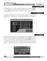
Program screen
provides you with a graphic
representation of the configuration of the individual ZonePro unit, including all the processing
modules and their positions in the signal path. The program screen also offers access to meters,
scene storing and loading, the Wizard functions, and file storing. Double clicking on the pro-
cessing modules take you to the Module view.
Module view
(also called
edit screen
) provides
access to the processing parameters. Editing of parameters is done in Module view.
Once the software has been loaded and the ZonePro unit is connected via the included Null
Modem cable, run the Graphic User Interface (GUI) by double clicking on the application icon.
You will see the ZonePro Designer window open with an icon of the ZonePro™ unit. Double
clicking on the unit will open the unit to the program screen where you will be able to see the
processing modules and the configuration. If the computer cannot connect to the ZonePro
device, check the COM port assignment under Network Properties in the Venue View, and make
sure that you are connecting to the correct COM port.
2. 3 - Connections
2. 2 - Views
2. 1 - ZonePro Philosophy
ZonePro
™
User Manual
Summary of Contents for Zone Pro 640
Page 1: ...User Manual 640 641 ...
Page 5: ...INTRO CUSTOMER SERVICE INFO Defining the ZonePro WARRANTY INFO INTRODUCTION 640 641 ...
Page 9: ... Getting Started Section 1 ZonePro ...
Page 13: ...SOFTWARE OPERATION Section 2 ZonePro ...
Page 17: ...SYSTEM SETUP Setup Section 3 ZonePro ...
Page 24: ...System Setup 16 Section 3 ZonePro ZonePro User Manual ...
Page 25: ...DETAILED PARAMETERS Detailed Parameters Section 4 ZonePro ...
Page 41: ...APPLICATION GUIDE Section 5 ZonePro ...
Page 42: ...Application Guide 34 SECTION 5 ZonePro ZonePro User Manual 5 1 Retail Install ...
Page 44: ...Application Guide 36 SECTION 5 ZonePro ZonePro User Manual 5 2 Restaurant Bar Install ...
Page 46: ...Application Guide ZonePro User Manual 38 Section 5 ZonePro 5 3 Health Club Install ...
Page 48: ...Application Guide ZonePro User Manual 40 Section 5 ZonePro 5 3 Night Club Install ...
Page 50: ......
Page 51: ... Appendix ZonePro ...


