System Setup
®
12
Section 3
ZonePro
™
ZonePro
™
User Manual
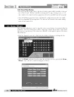
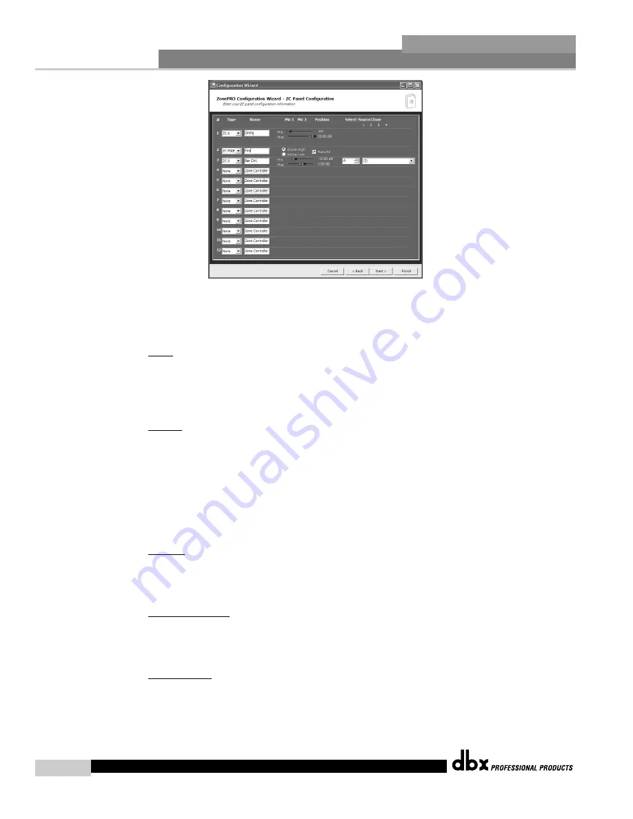
3.2.3 ZC Panel Configuration
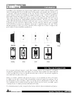
The ZC Panel Configuration Page allows setup of wall-mounted Zone Controllers to be used
with the ZonePro unit.
ID #s -
The ID numbers on the left side of the window correspond to the identification num-
ber set using the DIP switches on the individual zone controllers. ID 1-6 are connected to one
of the ZC inputs on the rear panel and ID 7-12 are connected to the other input. For ID 7-12
add 6 to the ID # selected on the back of the ZC. For example, if I am connecting to input 7-
12 and I am connecting a ZC with ID #3 selected this would be ID #9.
Names -
The zone controllers can be named to eliminate confusion in later menus.
Since several zone controllers have multiple functions examples of each function will be shown:
Scenes - To change scenes a ZC-3 or ZC-4 must be used in the ID #1 position. This zone con-
troller must have the scene check box checked. Select the desired scenes from the list of scenes
on the right hand side of the window and associate it with the selector position A, B, C, D on
a ZC-3 or switch position 1-16 on a ZC-4 (see ZC-4 switch positions within the Appendix).
Fire - The ZC-FIRE is a special case of scene selection. A ZC-FIRE can only be assigned to ID
#2. Select whether the ZC-FIRE should be activated when taken high or low. Select to either
Mute all outputs, or select the desired scene to be loaded.
Volume
- A ZC-1, ZC-2, ZC-6, or ZC-8 can be used to adjust volume. Select the desired ZC
type, and make sure it has the correct ID number. Set the maximum and minimum values for
this zone controller. As a default, all volume zone controllers can provide up to +20dB gain
boost and can cut to -Inf to mute.
Source Selection
- A ZC-3, ZC-4, or ZC-8 can be used to provide source selection. Select the
desired ZC type and make sure it has the correct ID number. for a ZC-3 or ZC-8, for each switch
position A-D select the corresponding source. For a ZC-4, select the switch position 1-16 and
choose the corresponding input source (see ZC-4 switch positions within the Appendix).
Page Routing
- To dynamically route or assign pages a ZC-3, ZC-4 or ZC-7 can be used. Select
the desired ZC type, and make sure it has the correct ID number. For a ZC-3 only four zones
or groups of zones can be switched between. Select which microphone is to be dynamically
routed with this zone controller; for each position of the ZC-3 select the zones that are to to be
paged by checking in the boxes for each zone output. A ZC-4 can switch between 16 zones
or groups of zones. First choose which of the two microphones is to be routed with this zone
Summary of Contents for Zone Pro 640
Page 1: ...User Manual 640 641 ...
Page 5: ...INTRO CUSTOMER SERVICE INFO Defining the ZonePro WARRANTY INFO INTRODUCTION 640 641 ...
Page 9: ... Getting Started Section 1 ZonePro ...
Page 13: ...SOFTWARE OPERATION Section 2 ZonePro ...
Page 17: ...SYSTEM SETUP Setup Section 3 ZonePro ...
Page 24: ...System Setup 16 Section 3 ZonePro ZonePro User Manual ...
Page 25: ...DETAILED PARAMETERS Detailed Parameters Section 4 ZonePro ...
Page 41: ...APPLICATION GUIDE Section 5 ZonePro ...
Page 42: ...Application Guide 34 SECTION 5 ZonePro ZonePro User Manual 5 1 Retail Install ...
Page 44: ...Application Guide 36 SECTION 5 ZonePro ZonePro User Manual 5 2 Restaurant Bar Install ...
Page 46: ...Application Guide ZonePro User Manual 38 Section 5 ZonePro 5 3 Health Club Install ...
Page 48: ...Application Guide ZonePro User Manual 40 Section 5 ZonePro 5 3 Night Club Install ...
Page 50: ......
Page 51: ... Appendix ZonePro ...


