SC 32 / SC 64
187
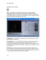
2dB over the threshold the Compressor will reduce the gain with a resulting
signal that is 1dB over the threshold. For light compression, choose a lower ratio,
while heavy compression requires a higher ratio. A setting of Inf:1 makes the
Compressor act as a limiter.
Gain Fader
- This parameter is used to compensate for the gain lost during
compression. By using heavy compression on a signal and then boosting the
signal with the ‘make-up’ Gain, the user can create a signal that sounds much
louder than it actually is.
Auto Button On/Off
- When Auto mode is on, the algorithm dynamically sets the
Attack, Hold, and Release times for the Compressor. The Auto mode constantly
adjusts these parameters in real time for optimum performance from the
Compressor. You will find that for most applications, not only is using the Auto
mode faster and easier but by letting the Compressor constantly tweak these
parameters for you will result in a better end result.
Attack Fader
- Attack is how fast the Compressor starts to compress the signal
after it passes the Threshold. Fast attack is useful when dealing with very fast
transients. The Attack fader is not active when in Auto mode.
Hold Fader
- Hold is the time the compressor remains in compression mode
after the signal has dropped below the Threshold. A longer hold time is useful in
smoothing out the sound when compressing several fast peaks that are fairly
close together in time. The Hold fader is not active while in Auto mode.
Release Fader
- Release is how fast the signal comes out of compression. The
Release is in dB per second. For example, if Release is set to 5 dB /sec, and the
signal is at 10dB of gain reduction, the release time is 2 seconds. Having a
release time that is either too fast or too slow for the signal can result in audible
artifacts called ‘pumping’ or ‘breathing’. This can cause volume drops in your
signal that may not be desired. The Release fader is not active while in Auto
mode.
Summary of Contents for SC 32
Page 1: ...SC32 SC64 Help ...
Page 2: ......
Page 5: ...1 SC 32 SC 64 SC 32 SC 64 Overview Philosophy ...
Page 8: ...SC32 SC64 Help 4 ...
Page 10: ...SC32 SC64 Help 6 ...
Page 25: ...SC 32 SC 64 21 Power Input SC 32 SC 64 Power Connector IEC power connector ...
Page 37: ...SC 32 SC 64 33 Edit Menu SC 32 SC 64 The Edit menu allows copy and paste functions ...
Page 39: ...SC 32 SC 64 35 This can be helpful when switching from editor to editor during programming ...
Page 61: ...SC 32 SC 64 57 One Group Added ...
Page 62: ...SC32 SC64 Help 58 Channels one Channel 1 and ten Channel 10 moved to the new group ...
Page 63: ...SC 32 SC 64 59 ...
Page 75: ...SC 32 SC 64 71 Channel 65 and Channel 70 moved to the new group ...
Page 76: ...SC32 SC64 Help 72 ...
Page 84: ...SC32 SC64 Help 80 ZC 2 ZC 3 ZC 4 ZC Fire ZC 6 ZC 7 ZC 8 ZC 9 ...
Page 94: ...SC32 SC64 Help 90 ...
Page 174: ...SC32 SC64 Help 170 ...
Page 176: ...SC32 SC64 Help 172 Input Gate GATE Input Inserts INS1 INS2 ...
Page 185: ...SC 32 SC 64 181 ...
Page 193: ...SC 32 SC 64 189 ...
Page 205: ...SC 32 SC 64 201 or select the Output DSP Inserts link ...
Page 206: ...SC32 SC64 Help 202 ...
Page 230: ...SC32 SC64 Help 226 ...


