background image

Speaker Placement 

Many loudspeakers are designed without regard to baffl e step loss. If a woofer has a midband sensitivity of 88 dB for 
example, and is mounted on a large infi nite baffl e (like your living room wall), it will maintain the 88 db sensitivity right 
down to it’s rated F3. All frequencies, even the large low frequency wavelengths are supported by the large wall.

But speakers are usually mounted in boxes with varying degrees of baffl e width. At a given frequency determined by 
the baffl e dimensions, the lower frequency wavelengths start to ‘wrap’ behind the baffl e. This is called a 2 pi to 4 pi 
transition and will result in a 6 dB loss in an anechoic chamber.

A typical two way speaker in a normal listening room will exhibit a 3 to 4 dB loss in the bass region. If left unchecked, 
most speakers will sound too thin with too much midrange output. 

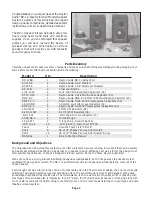
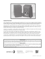
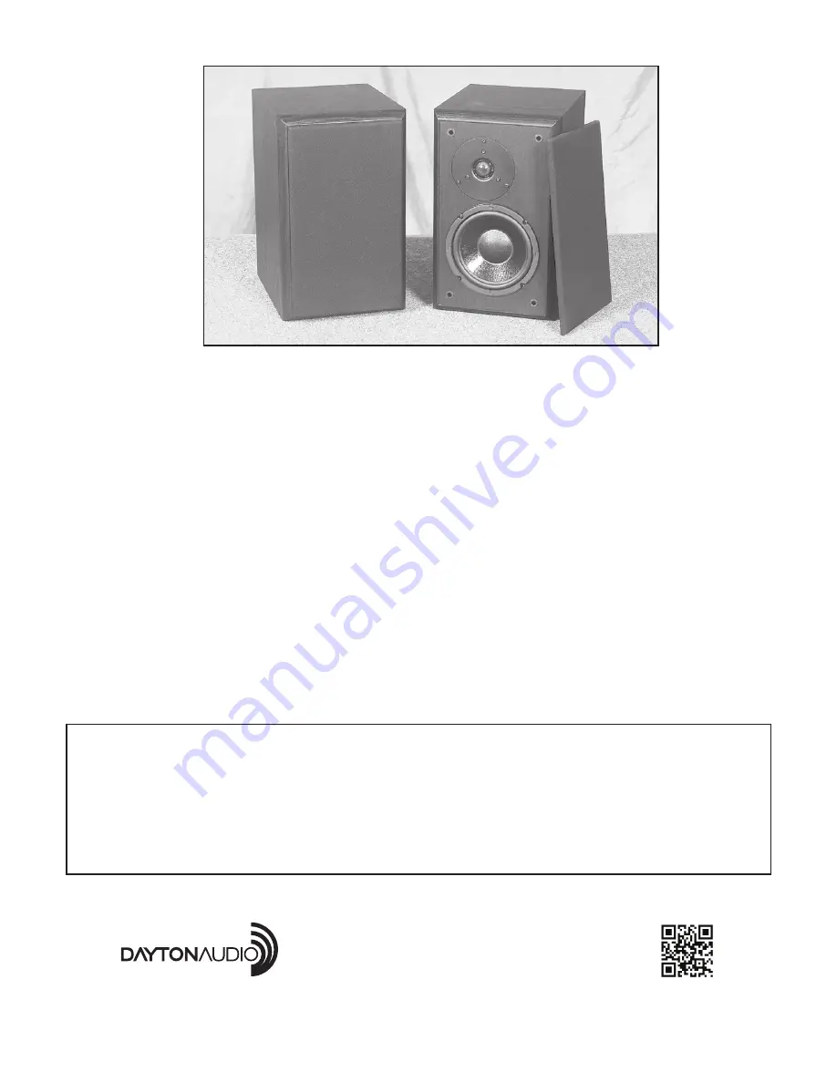
The BR-1 was designed with 4 dB of baffl e step compensation which results in surprising bass output for a 6-1/2" 
diameter woofer. The midband is rolled off to match the woofer’s natural in-room response to achieve the excellent 
bass performance. The trade off is a loss of some midband sensitivity, with an overall sensitivity of about 83 dB.

In most rooms, you will fi nd the BR-1 to sound best placed approximately 3 feet from the rear wall and mounted on ap-
propriate speaker stands. Ideally you want to place the speakers so they are at least 3-4 ft from side walls if possible. 

© Dayton Audio

®

Last Revised:  2/10/2015

daytonaudio.com

tel + 937.743.8248

[email protected]

705 Pleasant Valley Dr.

Springboro, OH 45066 

USA

Warranty Information

Dayton Audio products are constructed by industry experts, and are thoroughly tested before shipment. Dayton Audio products are warranted for the period of one 
year. This warranty is limited to manufacturer defects, either in materials or workmanship. Dayton Audio is not responsible for any consequential on inconsequential 
damage to any other unit or component or the cost for installation or extraction of any component of the audio system. In the rare case of a product failure, please 
contact your place of purchase or call our Customer Support Department at (937) 743-8248.

Warranty Limitations

There are no other warranties, either express or implied, which extend the foregoing, and there are no warranties of merchantability or fi tness for any particular 
purpose. The warranty will not cover incidental or consequential damage due to defective or improper use of products. This includes but is not limited to burnt voice 
coils, overheating, bent frames, holes in the cone, or broken lead wires.

This warranty gives you specifi c legal rights and you may also have other rights which vary from state to state.

Non-Warranty Service: If non-warranty service is required, the product may be sent to the Company for repair/replacement, transportation prepaid, by calling (937) 743-8248 
for details, complete instructions, and service fee charges.

Summary of Contents for BR-1

Page 1: ...2 WAYREFERENCE MONITOR SYSTEM Model BR 1 ConstructionWorkbook...

Page 2: ...er design Although cost was a factor the design must offer excellent performance In short a Budget Reference system Hence the name Dayton Audio BR 1 Many of you have a strong interest in building inex...

Page 3: ...on Audio 1 1 8 silk dome tweeter is hands down one of the finest tweeters available in it s price range The response exhibits some peakiness and the driver seems to have a wandering Fs but the sound i...

Page 4: ...and the Le was found to be 1 87 millihenries Using an accurate ohm meter the Re was 6 5 ohms Using the above formula R 1 25 x 6 5 R 8 125 ohms so C 00187 66 C 0000283 farads or 28 3 uF Although these...

Page 5: ...ayton Audio film foil capacitor wired in parallel The reason NP electrolytics are very cost effective but exhibit high ESR Equivalent Series Resis tance and also have some inductive components Using a...

Page 6: ...to achieve a flat overall response The BR 1 measures on axis within 2 0dB from 100 Hz 12 KHz Flat frequency response is desirable so that all frequencies are reproduced with the same loudness over the...

Page 7: ...be relatively benign however It s worth discussing the parallel notch filter because it is a handy circuit that is used to control frequency response peaks A parallel notch filter consists of a capac...

Page 8: ...relationship exists when the tweeter is connected with normal polarity Reverse Tweeter Polarity Page 8 So the values for our proposed parallel notch filter is a 9 4uF capacitor 26mH inductor and a 14...

Page 9: ...8 wide 14 1 4 high with a depth of 11 giving it a small footprint suitable for stand mounting It is recommended to place the tweeter at or slightly below ear height of a seated listener The center to...

Page 10: ...is critical to the proper operation of this speaker system In a worst case situation an improperly wired network can damage your receiver or amplifier Please double and triple check all values and wi...

Page 11: ...the insulation on all wires back about 3 8 1 2 6 Using a crimp tool crimp the 205 terminals on the wire leads To ensure a tight connection gently squeeze the push on terminals with a small pair of pli...

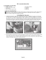
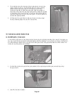
Page 12: ...point it is a good idea to label each wire to ensure proper hook up Masking tape and a marker will work fine 3 Cabinet Assembly Instructions A Installing the Crossovers To mount the crossovers we rec...

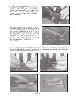
Page 13: ...stall Acoustic Damping Foam We ve included two 2 sheets of acoustic foam one sheet for each speaker Acoustic damping foam absorbs internal standing waves inside the cabinet and prevents reflections to...

Page 14: ...2 9 5 1 2 2 Install the foam on the back of the cabinet first and trim around the port tube Make sure it does not obstruct the airflow to the port tube as this will alter the tuning of the box 3 Next...

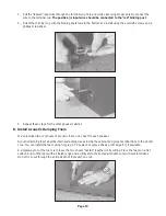
Page 15: ...allow the faceplate to mount flush with the baffle 1 Attach each wire to the appropriate driver terminals while observing proper polarity positive to positive negative to negative The tweeter has a r...

Page 16: ...ce the speakers so they are at least 3 4 ft from side walls if possible Dayton Audio Last Revised 2 10 2015 daytonaudio com tel 937 743 8248 info daytonaudio com 705 Pleasant Valley Dr Springboro OH 4...

Reviews: