background image

Page 14

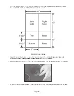
1.  The foam must be cut to fit internally on the right/left side walls, rear, top and bottom panels. Do not apply it 

to the front baffle. Cut the foam to the dimensions shown in Fig. 1.

FIGURE 1: Foam Cutting

18"

13"

11"

5-1/2"

9"

5-1/2"

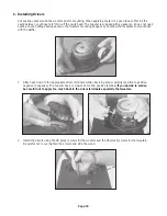
2.  Install the foam on the back of the cabinet first and trim around the port tube. Make sure it does not  

obstruct the airflow to the port tube, as this will alter the tuning of the box.

3.  Next install both sides and then top and bottom. The bottom piece of foam will simply lay on top of the crossover.

4.  Position the “labeled” woofer and tweeter lead wires through the foam and run to their respective driver openings. 

Summary of Contents for BR-1

Page 1: ...2 WAYREFERENCE MONITOR SYSTEM Model BR 1 ConstructionWorkbook...

Page 2: ...er design Although cost was a factor the design must offer excellent performance In short a Budget Reference system Hence the name Dayton Audio BR 1 Many of you have a strong interest in building inex...

Page 3: ...on Audio 1 1 8 silk dome tweeter is hands down one of the finest tweeters available in it s price range The response exhibits some peakiness and the driver seems to have a wandering Fs but the sound i...

Page 4: ...and the Le was found to be 1 87 millihenries Using an accurate ohm meter the Re was 6 5 ohms Using the above formula R 1 25 x 6 5 R 8 125 ohms so C 00187 66 C 0000283 farads or 28 3 uF Although these...

Page 5: ...ayton Audio film foil capacitor wired in parallel The reason NP electrolytics are very cost effective but exhibit high ESR Equivalent Series Resis tance and also have some inductive components Using a...

Page 6: ...to achieve a flat overall response The BR 1 measures on axis within 2 0dB from 100 Hz 12 KHz Flat frequency response is desirable so that all frequencies are reproduced with the same loudness over the...

Page 7: ...be relatively benign however It s worth discussing the parallel notch filter because it is a handy circuit that is used to control frequency response peaks A parallel notch filter consists of a capac...

Page 8: ...relationship exists when the tweeter is connected with normal polarity Reverse Tweeter Polarity Page 8 So the values for our proposed parallel notch filter is a 9 4uF capacitor 26mH inductor and a 14...

Page 9: ...8 wide 14 1 4 high with a depth of 11 giving it a small footprint suitable for stand mounting It is recommended to place the tweeter at or slightly below ear height of a seated listener The center to...

Page 10: ...is critical to the proper operation of this speaker system In a worst case situation an improperly wired network can damage your receiver or amplifier Please double and triple check all values and wi...

Page 11: ...the insulation on all wires back about 3 8 1 2 6 Using a crimp tool crimp the 205 terminals on the wire leads To ensure a tight connection gently squeeze the push on terminals with a small pair of pli...

Page 12: ...point it is a good idea to label each wire to ensure proper hook up Masking tape and a marker will work fine 3 Cabinet Assembly Instructions A Installing the Crossovers To mount the crossovers we rec...

Page 13: ...stall Acoustic Damping Foam We ve included two 2 sheets of acoustic foam one sheet for each speaker Acoustic damping foam absorbs internal standing waves inside the cabinet and prevents reflections to...

Page 14: ...2 9 5 1 2 2 Install the foam on the back of the cabinet first and trim around the port tube Make sure it does not obstruct the airflow to the port tube as this will alter the tuning of the box 3 Next...

Page 15: ...allow the faceplate to mount flush with the baffle 1 Attach each wire to the appropriate driver terminals while observing proper polarity positive to positive negative to negative The tweeter has a r...

Page 16: ...ce the speakers so they are at least 3 4 ft from side walls if possible Dayton Audio Last Revised 2 10 2015 daytonaudio com tel 937 743 8248 info daytonaudio com 705 Pleasant Valley Dr Springboro OH 4...

Reviews: