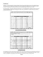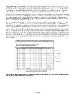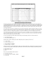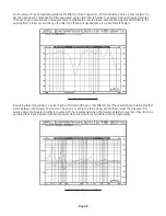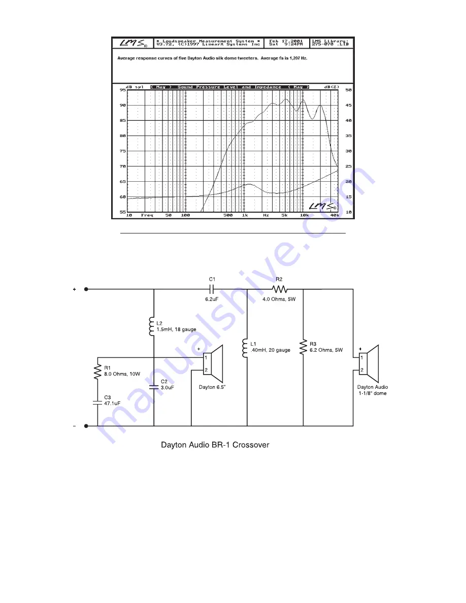
1-1/8" Dome On Axis Frequency Response and Impedance Sweep
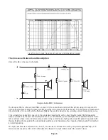
The low pass filter is a four element filter. L2 and C2 form an electrical 2nd order filter (a filter using 2 components to
yield an approximate 12dB per octave roll-off) and yields a 2nd order acoustic response. The impedance compensation
circuit consists of C3 and R1 which effectively flattens the woofer’s inductive rise, yielding a smooth impedance curve.
C3 is actually two capacitors, one a 47uf non-polarized electrolytic, with a .10uF Dayton Audio film/foil capacitor
wired in parallel. The reason? NP electrolytics are very cost effective, but exhibit high ESR (Equivalent Series Resis-
tance) and also have some inductive components. Using a small value high quality capacitor placed in parallel with
the electrolytic will also parallel the undesirable resistance and inductance, thus reducing them greatly. This method
is called bypassing.
The high pass filter is comprised of C1 and L1, and is also a electrical 2nd order yet it yields approximately a 3rd
order acoustic response. R2 and R3 attenuates the tweeter’s output 6 dB to match the woofer’s level.
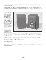
The Crossover Network and Description
Here is the BR-1 crossover schematic.
Page 5


