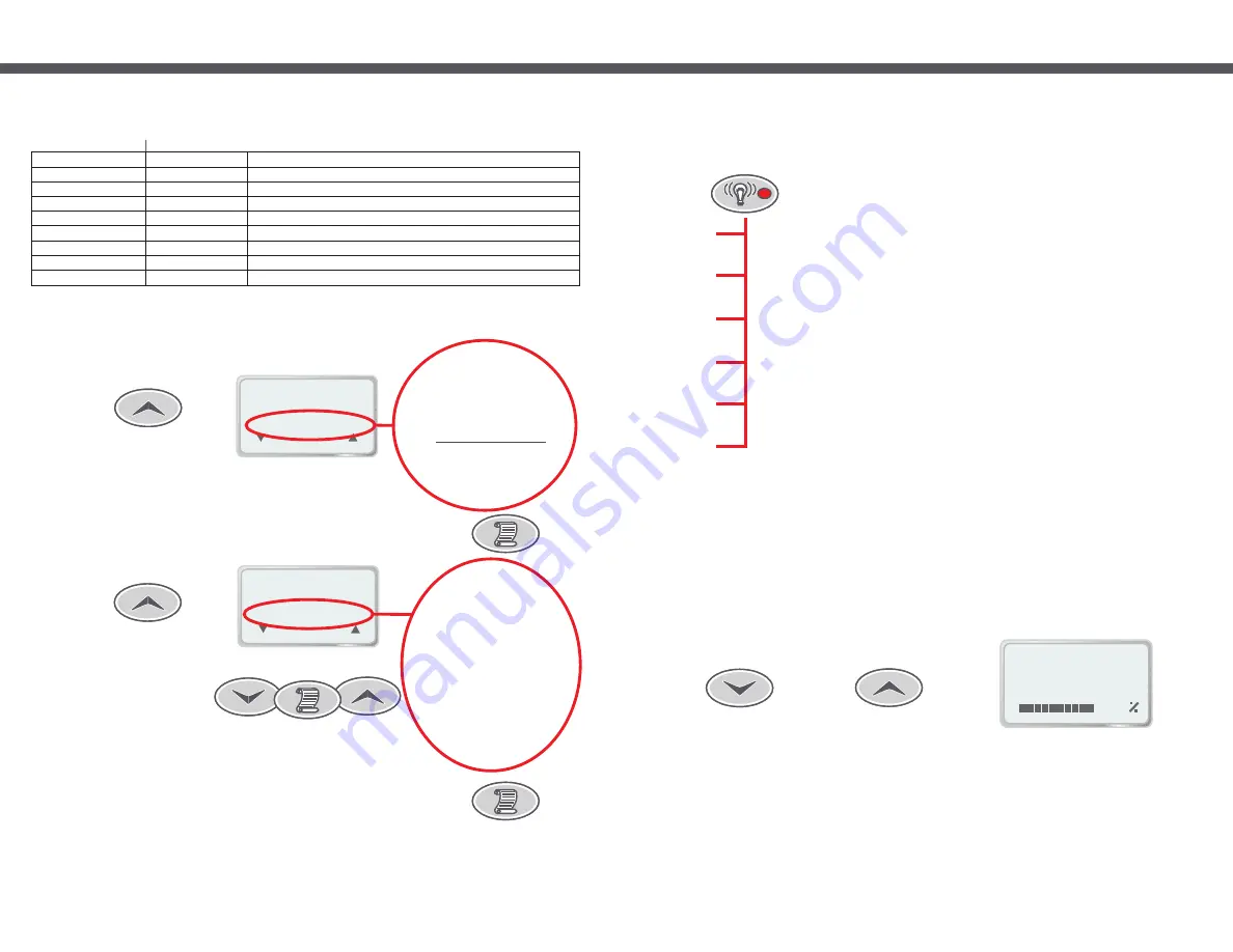
EFFECT SPEED:
100
36.75
C
O
Up
Down
Page 11
6.2 Light Effect Mode
Seven pushes of the Light Effect Mode button cycle the light mode setting as follows:
In addition to being able to change the light colour, the SP1200 also has the ability to produce various lighting effects
while cycling through each of the available colours. The Light Effect Mode, UP and DOWN buttons are used to
select the lighting effect or colour of choice.
6.2.1 Adjusting The Light Effect Mode Speed
This setting is saved and will be automatically restored next time you turn on the light.
When a light effect mode has been selected (“SMOOTH CHANGE” to “STEP CHANGE” see above) the speed at
which the light cycles through the available colours may be manually adjusted. On the first press of UP/DOWN the
LCD will display “EFFECT SPEED” along with a bar graph showing the current setting. While viewing this display you
may press the UP and DOWN buttons to adjust the cycle speed as required. Hold down either button for automatic
key press repeat. At the maximum setting of 100% the speed is approximately 40 times faster than the minimum
setting of 2% and approximately 6 times faster than the default setting of 50%. The setting for each light effect is
saved individually and will be restored next time you select the given light effect mode.
Push 1
(Light On)
Push 2
(Change Colour)
Push 3
(Change Effects)
Push 4
(Change Effects)
Push 5
(Change Effects)
Push 6
(Change Effects)
Push 7
(Change Effects)
LCD Displays “FIXED WHITE”, Light is pure white, no light effect.
Pressing either the UP or DOWN button selects the Preset Colour mode (see below)
LCD Displays “PRESET COLOUR”, Light colour depends on previous selection (default white). The UP and
DOWN buttons can be used to select a different colour of choice. Your chosen colour is saved and will be
automatically restored next time you select Preset Colour mode.
LCD Displays “SMOOTH CHANGE”, Light cycles through all of the available colours continuously without any
delay for each colour. The UP and DOWN buttons may be used to change the speed of the light effect (see
section 6.2.1 below).
LCD Displays “FADE UP/DOWN”, Light cycles through all of the available colours one at a time. Each colour is
faded in from zero intensity (light off) and then faded out to zero intensity. The UP and DOWN buttons may be
used to change the speed of the light effect (see section 6.2.1 below).
LCD Displays “STEP CHANGE”, Light cycles through all of the available colours one at a time without any
smooth fading between different colours. The UP and DOWN buttons may be used to change the speed of the
light effect (see section 6.2.1 below).
LCD Displays “DELAYED CHANGE”, Light cycles through all of the available colours one at a time. Each colour
is shown for a short period then the light will quickly fade to the next colour. The UP and DOWN buttons may be
used to change the speed of the light effect (see section 6.2.1 below).
LCD Displays “BURST UP/DOWN”, Light cycles through all of the available colours one at a time. Very similar
to FADE UP/DOWN, except that the colour fades in very fast and fades out slowly. The UP and DOWN buttons
may be used to change the speed of the light effect (see section 6.2.1 below).
Notes:
1) The UP and DOWN buttons are shared with Light Level, Light Mode, SPVSB speed and the menu system.
When not within the menu system the actual use of the UP and DOWN buttons depends on which of the three
function buttons was pressed last - Light Level, Light Mode or Air.
2) Pressing either Light Level or Light Mode buttons while the light is on will only cycle through the available options
when the LCD is displaying the current selection. This allows you to set the function of the UP and DOWN
buttons and to view the current Light Level or Light Mode setting without changing them.
3) Pressing Light Mode button when light is off will turn on the light using Light Level High.
4) By default the touch pad panel backlight will mirror the pool setting, but this feature may be disabled. See
section 7.8.7 on page 26
Page 22
1. General service
2. Cabinet service
3. Replace filter
4. Ozonator
5. Custom #1
6. Custom #2
7. Custom #3
8. Custom #4
9. Custom #5
7.7.1 Maintenance Timer Configuration
The installer, serviceman or owner can fill in the table below to help keep track of what
settings have been entered into the controller.
Timer name
Period (weeks) Description/notes
7.7.2 Acknowledging a maintenance timer
Push 6
1. SET TEMP
2. USER TIMER
3. CLOCK
4. USER ALARM
5. SLEEP TIMES
7. MISC OPTIONS
8. ADV. OPTIONS
9. LD. DEFAULTS
6. MAINT TIMERS
6.
MAINT. TIMERS
- - - -
(SUBMENU)
(
)
(
)
1) Select MAIN menu then push UP button six times
(OPTIONS)
(
)
(
)
- - - -
1.
GENERAL SRVC
1. GENERAL SRVC
2. CABINET SRVC
3. REPLACE FLTR
4. OZONATOR
5. CUSTOM #1
6. CUSTOM #2
7. CUSTOM #3
8. CUSTOM #4
9. CUSTOM #5
Scroll to SET
3) Press the SCROLL button to begin modifying the timer options.
Once a timer is due you need to manually clear it - it will not clear by itself. Follow these steps to clear a maintenance
timer that is currently due:
2) Press the SCROLL button then the UP button as required to select the
maintenance timer to be cleared.


