10: Display Board
10-6
PRC1099A-MS
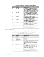
10.2.4
J4 Connector
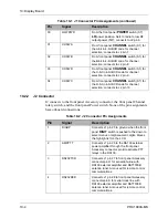
J4 connects to front panel Power, Mode, and Tune switches, and CW Key and
PTT lines on the Audio and Accessory connectors.
7
ANTSW
Connects J1 pin 21 to ground when an
antenna is installed in the Whip antenna
connector.
8
CHSET/TUNE
Connects J1 pin 22 to ground when the front
panel
WHIP TUNE
button is pressed to
initiate a tune cycle and save tune data for
the selected antenna tuner.
9
HANDSET
Not used; connects J1 pin 23 and J3 pin 3
through jumper LK1.
10
AMPALC
Connects J1 pin 24 to a RA100 external RF
amplifier through the front panel Accessory
connector pin N.
ALC signal from the RA100 ALC to activate
PRC1099A ALC circuitry.
Table 10-3 J3 Connect Pin Assignments (continued)
Pin
Signal
Description
Table 10-4 J4 Connect Pin Assignments
Pin
Signal
Description
1
OPTSW
Connects J1 pin 1 to ground through the front
panel
MODE
switch
OPT
position.
2
LSBSW
Connects J1 pin 3 to ground when the front
panel
MODE
switch is set to the
LSB
position to select lower side band mode.
3
SLEWDN
Connects J1 pin 5 to ground through the front
panel
TUNE
switch is pushed to the down
position to move down through selections
and settings within menus on the LCD.
4
SLEWUP
Connects J1 pin 6 to ground when the front
panel
TUNE
switch is pushed to the up
position to move up through selections and
settings within menus on the LCD.
5
SQUELCH
Connects J1 pin 7 to ground when the front
panel
MODE
switch is set to the
SQUELCH
position to disable squelch.
6
SPARE1
Connects J1 pin 11 to open connection.
7
SPARE2
Connects J1 pin 13 to open connection.


