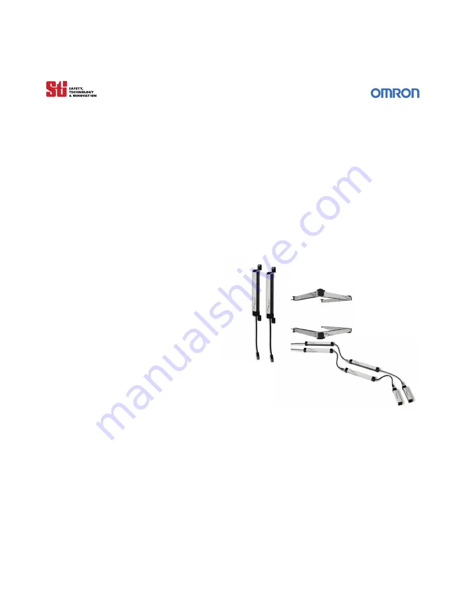
background image

. . . . .

4700 Series

Installation and Operating Manual

for MC4700, MCF4700, MCJ4700, MS4700 & MSF4700 Series

Original Instructions

O M RO N ScientificTechnologiesInc.

Manufacturing and Sales Office

6550 Dumbarton Circle

Fremont CA 94555 USA

1 / 888 / 510-4357

Tel: 510/608-3400

Fax: 510/744-1442

www.sti.com

© OSTI 1209 PN99584-0050 Rev.E

Summary of Contents for MC4700

Page 1: ...0 MCJ4700 MS4700 MSF4700 Series Original Instructions O M RO N Sc i e nt i f i cTe c hnol ogi e sI nc Manufacturing and Sales Office 6550 Dumbarton Circle Fremont CA 94555 USA 1 888 510 4357 Tel 510 608 3400 Fax 510 744 1442 www sti com OSTI 1209 PN99584 0050 Rev E ...

Page 2: ...transmitters and receivers for use with both the LCM metal enclosure as well as the DIN box controller Where information is common the term 4700 system is used Where information is specific to a certain version the exact model number example safe mounting distance calculation is provided The specifications and detailed information of the MCF4700 MCJ4700 MS4700 and the MSF4700 information are locat...

Page 3: ...d indicators page 13 Section 4 System Operation page 16 4 1 Operating States page 16 4 1 1 Machine Run page 16 4 1 2 Machine Stop page 16 4 1 3 Interlock page 16 4 1 4 Alarm page 16 4 2 Operating Modes page 16 4 2 1 Automatic Start page 16 4 2 2 Start Interlock page 17 4 2 3 Start Restart Interlock page 17 4 3 Operating Mode Selection page 18 4 4 Start Switch Type Selection page 18 Section 5 Detec...

Page 4: ... 4 2 Interlock Status page 26 6 4 3 Alarm Status page 26 6 4 4 Exact Channel Select and Floating Blanking Status page 26 Section 7 Outputs page 27 7 1 Safety Outputs page 27 7 1 1 Din Controller and Metal Chassis Solid State Version page 27 7 2 2 metal chassis Controller Relay Output Version page 27 7 2 Auxiliary Outputs page 27 7 2 1 DIN Controller and Metal Chassis Solid State Version page 27 7 ...

Page 5: ...cial Requirements for Perimeter Guarding page 36 9 3 8 Presence Sensing Device Initiation page 36 Section 10 Connecting To The Machine Control Circuit page 37 10 1 Din Controller page 37 10 1 1 Connecting to a Safety Monitoring Device page 38 10 1 2 Connecting Via an RM 1 Module page 39 10 1 3 Connecting Via Two Force Guided Relays page 40 10 2 Metal Chassis Controllers page 41 10 2 1 Connecting V...

Page 6: ...ge 55 14 3 2 MCF4700 Spare Parts page 60 14 4 MicroSafe Jointed MCJ4700 Series page 65 14 4 1 MCJ4700 Segment Dimensions page 65 14 4 2 90 Jointed MicroSafe MCJ4700 Dimensions page 56 14 4 3 Sensor Assembly Instructions page 56 14 4 4 Installation page 56 14 4 5 Minimum Object Resolution at Joints page 56 14 4 6 MCJ4700 Spare Parts page 56 14 5 MiniSafe MS4700 Series page 71 14 5 1 MS4700 Dimensio...

Page 7: ...age 92 C 1 Introduction page 92 C 2 Features page 92 C 2 1 System identification page 92 C 2 2 System status page 92 C 2 3 System Settings page 92 C 2 4 Diagnostic Information page 93 C 3 Basic DeviceNet Network Connections page 95 C 4 LCM 2XX series internal D Net Wire Colors and Pin Outs page 95 C 4 1 Screw Connectors for LCM 2XX series D Net interface module page 95 C 5 DeviceNet Configuration ...

Page 8: ...ignment Example page 32 Figure 9 5 Minimum Distance from a Reflective Surface as a Function of Range page 32 Figure 9 6 Correct Light Curtain Installation Examples page 34 Figure 9 7 Multiple Light Curtain Installation Configurations page 35 Figure 9 8 Mounting Orientation page 35 Figure 10 1 Connecting to a Safety Monitoring Device page 38 Figure 10 2 Connecting via an RM 1 Module page 39 Figure ...

Page 9: ... LCM 1 LCM 2 and LCM 3 Controllers page 14 Table 4 1 Operating Mode Switch Settings page 18 Table 5 1 System Response to Exact Channel Select page 19 Table 5 3 System Response to Floating Blanking page 21 Table 5 4 Icon Key for Tables 5 1 and 5 2 page 21 Table 5 5 Sample S and Dpf Factors for 12 mm Resolution Systems page 22 Table 5 6 Sample S and Dpf Factors for 14 mm resolution Systems page 22 T...

Page 10: ...er and Receiver Model Number page 57 Table 14 10 MCF4700 12 Dimensions First Middle Segment page 59 Table 14 11 MCF4700 12 Dimensions Last Segment page 59 Table 14 12 MCF4700 14 MCF4700 20 and MCF4700 30 First and Middle Segment page 59 Table 14 13 MCF4700 14 MCF4700 20 and MCF4700 30 Last Segment page 60 Table 14 14 Transmitter and Receiver Segments page 60 Table 14 15 MCJ470 12 Dimensions page 6...

Page 11: ...ress with a full revolution clutch The guarded machine must not present a hazard from flying parts The guarded machine must have a consistent stopping time and adequate control mechanisms Severe smoke particulate matter and corrosives may degrade the efficiency of a safety light curtain Do not use a 4700 system in this type of environment All applicable governmental and local rules codes and regul...

Page 12: ...vidual Beam Indicators External Device Monitoring MPCE Monitoring Automatic Start Mode Start Interlock Mode Start Restart Interlock Mode Adjustable Mounting Brackets Floating Blanking Exact Channel Select Two Safety PNP Outputs Auxiliary Output Start Switch Input Selectable NO or NC 2 2 OPTIONAL FEATURES Relay Safety Outputs Metal Chassis Controllers only DeviceNet Multi Channel Select Non CE ...

Page 13: ...es is gained by the following procedure 1 Remove the four screws holding the cover in place see Figure 3 1 for location 2 Place the blade of a thin flat blade screwdriver between the cover and the main controller housing and gently lift the cover off See Figure 3 1 for detail The cover is not hinged and will be completely removed To replace the cover 1 Correctly position one end and push down on t...

Page 14: ...8 510 4357 S TI Label P N 28621 0010 re TEST PR O CEDU R E sides and bottom of the sensing field and up and down through the center of the sensing field Verify that the Redindicator is ON andtheGreenindicator is OFF while the test object is anywhere in the sensing field watch for any unprotected access to the point of hazard 6 Start the machine Interrupt the sensing field with the test object T he...

Page 15: ...lect or Floating Blanking Indicator Amber 4 Interlock or Fault Indicator Yellow 5 Machine Stop Indicator Red 6 Machine Run Indicator Green 7 TRANSMITTER 8 Detection Zone for the 4700 Transmitter and Receiver 2 YEL 4 RED STOP BLOCKED 3 GRN RUN CLEAR 2 YEL INTERLOCK OR CHANNEL SELECT 1 AMBER FLOATING BLANKING 1 AMBER 4 RED 3 GRN INDICATORS LED RECEIVER DETECTION ZONE TRANSMITTER MC4700 MC4700 2 YEL ...

Page 16: ...12 11 9 10 15 14 16 13 17 NOTE For DeviceNet Option LCM 2 S eries Terminals 13 to 17 are indicated below 13 14 15 DeviceNet C AN DATA H 16 17 DATA L C AN VÐ 13 LCM 1 Series Fremont CA US A Tel 510 608 3400 Fax 510 744 1442 www sti com Scientific T echnologies Inc OS S D 1 OS S D R E T UR N MP C E 0 V DC MP C E R E T UR N B L U E AUX1 OUT OR ANGE OS S D 2 AUX2 OUT B L AC K P IN K G R A Y V I O L E ...

Page 17: ...oint of hazard 6 Start the machine Interrupt the sensing field with the test object T he machine should stop immediately Never insert the test object into the dangerous parts of the machine With the machine at rest interruptthesensingfieldwiththetestobject that the machine will not start with the test object in the sensing field 7 Ensure the braking and machine stop systems are working properly in...

Page 18: ...3 INTERLOCK The two system safety outputs are in the OFF state the red machine stop indicator and yellow interlock indicator are lit The auxiliary output is in a state consistent with its configuration See Section 7 on page 27 The interlock state does not allow the protected machine to operate until the detection zone is clear of obstructions and the start button is pressed and released 4 1 4 ALAR...

Page 19: ...T RESTART INTERLOCK The 4700 system will power up with its safety outputs OFF and if no faults are detected enter the interlock state To enter the machine run state the detection zone must be clear or an exact channel select pattern satisfied and then the operator must press and release the start switch In the machine run state when an object is sensed entering the detection zone the 4700 will cha...

Page 20: ...etween the type of Start selected and used i e jumper between Pins 1 and 2 and Normally Open Start Switch used the switch must be pressed and released twice before the system will enter a Run state 5 DETECTION OPTIONS 5 Warning Use of Exact Channel Select and or Floating Blanking will make the 4700 system less sensitive to objects in the detection zone Improper use of either can result in severe i...

Page 21: ...ctive Table 5 1 Channel Select Status Exact Channel Select Inactive Exact Channel Select Inactive Exact Channel Select Active Exact Channel Select Active Exact Channel Select Active Channel 1 Channel 2 Channel 3 Channel 4 Channel 5 System Response machine run machine stop machine run machine stop machine stop System Response to Exact Channel Select 5 2 MULTI CHANNEL SELECT MCS MCS stores up to fou...

Page 22: ...0 Rev E Original Instructions 20 Figure 5 1 Connection Recommendations for LCM Metal Enclosure RET ECS 2 ECS 1 LCM 3 SW2 SW1 LCM 3 Out 1 Out 0 0vdc ref PLC Switch Selection Connection PLC Selection Connection 24 VDC Earth 0 vdc 7 6 5 4 3 2 1 RET ECS 2 ECS 1 24 VDC Earth 0 vdc 7 6 5 4 3 2 1 Figure 5 2 Connection Recommendations for LCM DIN Box Switch Switch 2 Switch 1 Pattern1 0 0 Pattern 2 0 1 Pat...

Page 23: ...p System Response to Floating Blanking Table 5 4 Symbol Description Optical channel is not blocked Optical channel is blocked Optical channel is selected by Exact Channel Select Optical channel is selected by Exact Channel Select and is blocked Icon Key for Tables 5 1 and 5 2 5 4 USING EXACT CHANNEL SELECT WITH FLOATING BLANKING Warning Using Exact Channel Select with Floating Blanking is an advan...

Page 24: ... inches 111 75 mm 5 Beams 47 mm 1 85 inches 5 35 inches 135 93 mm etc Sample S and Dpf Factors for 12 mm Resolution Systems Table 5 6 Total Number of Beams Disabled by Exact Channel Select and or Floating Blanking Minimum Object Resolution S Depth Penetration Factor Dpf for use with ANSI Formula Dpf 3 4 S 276 inches None 14 mm 0 55 inches 0 9 inches 24 mm 1 Beam 25 mm 0 98 inches 2 4 inches 61 mm ...

Page 25: ...igure 5 3 Adding Hard guarding to Light Curtain when Using Channel Select 5 5 ACTIVATING AND PROGRAMMING EXACT CHANNEL SELECT Warning To prevent unauthorized modification of the sense field the system controller should be installed in an enclosure with supervisor controlled access Exact Channel Select is activated by setting position 4 of Switches A and B located under the controller cover Refer t...

Page 26: ...cleared NOTE Replace controller cover after changing system configuration See Section 3 1 1 on page 11 and Section 3 1 2 on page 12 for details SWITCH A SWITCH B OPERATING MODE 4 5 6 4 5 6 Exact Channel Select Active CLOSED ON CLOSED ON Exact Channel Select Inactive default setting OPEN OFF OPEN OFF One channel Floating Blanking Active CLOSED ON OPEN OFF CLOSED ON OPEN OFF Two channel Floating Bla...

Page 27: ...on It monitors the 4700 system interface to the guarded machine and checks to ensure that the control elements are responding correctly to the light curtain and to detect any inconsistency between the two machine MPCE Connections for MPCE monitoring are made at the controller on terminals 10 and 11 for the DIN controller and on TB7 terminals 1 and 2 for the metal chassis controller For a detailed ...

Page 28: ... ON position located on the main controller board of the metal chassis controllers Position 3 of the dipswitch does not affect the operation of Relay version controller 6 4 STATUS INDICATOR LIGHTS The following status indicator lights are found on both the receiver and the controller 6 4 1 SAFETY OUTPUT STATUS When the 4700 system is in the machine run state the green indicator LEDs on the receive...

Page 29: ...y outputs to provide Run Stop signals to the guarded machine In the Run state the N O contacts are closed and will conduct the supplied voltage In the Machine Stop state the N O contacts are open The N C contact will open in a Run state and close in a Stop state 7 2 AUXILIARY OUTPUTS 7 2 1 DIN CONTROLLER AND METAL CHASSIS SOLID STATE VERSION Two auxiliary outputs are provided Auxiliary output AUX1...

Page 30: ... distance Regardless of the calculated distance a 4700 system should never be mounted closer to the point of operation hazard than allowed by Table 0 10 in OSHA 1910 217 Figure 8 1 Safe Mounting Distance 8 1 US SAFE DISTANCE FORMULAS In the United States two formulas exist to properly determine the safety distance STI recommends the formula provided by the American National Standards Institute ANS...

Page 31: ...rmation Dpf This is related to the minimum object sensitivity of the 4700 system By knowing the minimum object sensitivity S of the 4700 system Dpf is read directly from Table 5 5 Table 5 6 Table 5 7 or Table 5 8 For a 4700 system with 12 mm minimum object resolution and without Exact Channel Select or Floating Blanking active S 0 47 inches 12 mm and Dpf 0 67 inches 16 96 mm For a 4700 system with...

Page 32: ...a S K x T C where S the minimum distance in millimeters from the danger zone to the detection point line plane or zone K 1600 mm s T the overall system stopping performance in seconds T t1 t2 t1 response time of the safety light curtain in seconds This response time is given in Table 14 1 Table 14 2 and Table 14 3 t2 maximum stopping time of the machine is seconds C 850 mm i e S 1600 mm s x T 850 ...

Page 33: ...Appendix B must be used to test for this condition Trans mitter R eceiver Approach direction Central beam Light beam interrupted d R eflective S urface Interruption a B eam Angle a Operating R ange R Figure 9 1 Correct Mounting Example with Proper Alignment The interruption is clearly detected The reflective object is outside of the beam angle Trans mitter R eceiver Approach direction Central beam...

Page 34: ...from a Reflective Surface as a Function of Range 9 2 CONNECTING TRANSMITTER AND RECEIVER TO CONTROLLER 9 2 1 CABLE ASSEMBLIES Receiver cable connectors are color coded red and transmitter cable connectors are color coded black 9 2 2 CABLE CONNECTIONS Transmitter and receiver connections are made at terminal positions 23 through 34 Insert and secure the appropriate color conductor in the numbered p...

Page 35: ...ceiver Tan 4 Receiver Yellow 5 Receiver Red 6 Receiver Grey 7 Receiver Violet 8 Receiver Pink TB6 Terminals Component Conductor Color 1 Transmitter White 2 Transmitter Brown 3 Transmitter Blue 4 Transmitter Black 5 Transmitter Orange Metal Chassis Controllers 27 Transmitter and Receiver White 28 Transmitter and Receiver Brown 29 Receiver Pink 30 Receiver Violet 31 Receiver Gray 32 Receiver Tan 33 ...

Page 36: ...o the point of hazardous operation not guarded by the 4700 system must be protected by suitable means such as a fixed barrier guard an interlocked guard or a safety mat See Figure 9 6 Hazard Zone Ds L IG HT C UR T A IN Mechanical B arrier S upplemental Guarding E xample Supplemental Guarding Supplemental Guarding Supplemental Guarding Supplemental Guarding Figure 9 6 Correct Light Curtain Installa...

Page 37: ... ugges ted Trans mitter R ec eiver Trans mitter R ec eiver Machine 1 Machine 2 PR E FE R R E D INS TALLATION The receivers are mounted back to back Machine 1 Trans mitter Trans mitter R ec eiver Machine 2 R ec eiver NOT R E COMME NDE D INS TALLATION This arrangement may be s ubject to interference between the two light curtains Figure 9 7 Multiple Light Curtain Installation Configurations Beam sta...

Page 38: ... from 24 VDC 20 2 25A Power to the 4700 system must come from a dedicated power supply which must meet the requirements of IEC60204 1 and IEC 61496 1 STI part number 42992 or equivalent The 4700 system internally generates voltages for its own use No other devices should be connected to these voltages Internal consumption of power by the controller is less than 10 watts 415mA AC metal chassis cont...

Page 39: ...trical system only Never connect the 4700 to a positive ground protective earth system With a positive ground protective earth wiring scheme certain simultaneous shorts of both safety outputs may not be detected and the guarded machine may not stop resulting is severe operator injury WARNING Never use only a single safety output to control the machine Should this single output fail the machine may...

Page 40: ...he MPCE monitoring function OSSD RTN TAN MPCE AUX 1 OUT GRAY VIOLET WHITE DATA L CAN V START RETURN PINK BLACK 24VDC BLUE LCM Controller ORANGE BROWN OSSD1 0 VDC START MPCE RETURN DATA H CAN V OSSD 2 AUX 2 OUT YELLOW RED FB CS Interlock Stop Run Receiver Transmitter MPCE 2 24 VDC EARTH 0 VDC POWER SUPPLY LCM INPUT 1 LCM INPUT 2 SAFETY INTERLOCK INPUTS OTHER SAFETY DEVICES Safety Monitoring Device ...

Page 41: ...K 24VDC BLUE RM1 MODULE ORANGE BROWN OSSD1 0 VDC START MPCE RETURN DATA H CAN V OSSD 2 AUX 2 OUT YELLOW RED FB CS Interlock Stop Run Receiver Transmitter MPCE 2 MPCE 1 24 VDC GROUND 0 VDC POWER SUPPLY 2 25A 24 VDC 54VA TAN VIOLET 34 33 32 31 30 29 28 27 26 25 24 23 22 21 20 19 18 Must be accessible only by key Arc Suppressor 42 41 32 31 24 23 14 13 OSSD 1 OSSD 2 0 VDC Monitor MPCE 1 Arc Suppressor...

Page 42: ...iliary Output 1 NPN 100 mA max 30 VDC max Auxiliary Output 2 PNP 500 mA max Vsupply 2V For the purpose of bench testing prior to installation the user may select MPCE OFF In this case the MPCE input must be connected to MPCE RETURN MPCE monitoring must be used when force guided relays are used as the Final Switching Devices Connect the MPCE output to MPCE RETURN through the NC contacts 2 3 4 5 1 2...

Page 43: ...talled across the coils of the machine control relays Never install arc suppressors across the contacts of the safety light curtain Failure of the arc suppressor in a short condition across the contacts will result in an unsafe condition No external power is to be applied to terminals on TB7 The relay contacts on the MPCE1and MPCE2 must be force guided contacts To activate this function Jumper 2 o...

Page 44: ...relays Never install arc suppressors across the contacts of the safety light curtain Failure of the arc suppressor in a short condition across the contacts will result in an unsafe condition No external power is to be applied to terminals on TB7 The relay contacts on the MPCE1and MPCE2 must be force guided contacts To activate this function Jumper 2 on the main board needs to be installed in the O...

Page 45: ...type devices are supplied in the documentation kit No external power is to be applied to terminals on TB 7 and TB8 The relay contacts on the MPCE1and MPCE2 must be force guided contacts To activate this function pos 3 on SWA SWB must be active A jumper is needed when MPCE is inactive See figure 3 5 item 14 and 16 A N C or N O Remote Start input is selectable a momentary N O contact is shown The se...

Page 46: ...elay contacts on the MPCE1and MPCE2 must be forced guilded contacts The Safety Monitoring Device Must Monitor the MPCE s Normally Closed Contacts Suppression devices should be installed across the coils of the machine control relays Two diode type devices are supplied in the Documentation Kit A N C or N O Remote Start input is selectable a momentary N O contact is shown The Selection jumper Jumper...

Page 47: ...Procedure in Appendix B be performed at least once a year Testing ensures that the light curtain and the machine control system work properly to stop the machine Failure to test properly could result in serious injury to personnel The Test Procedure must be performed by qualified personnel To test the 4700 system without Exact Channel Select and Floating Blanking disabled use the STI supplied test...

Page 48: ... an obstruction or b that those areas not blocked by an obstruction are protected by supplemental guarding If neither of these conditions can be met the safe mounting distance of the 4700 system should be modified in accordance with the safe mounting distance formulas presented in Section 8 Safe Mounting Distance 3 Using a proper size test object and the method described in Section 11 3 Using the ...

Page 49: ...23 Invalid switch settings 1 Check channel select and MPCE switches for valid settings Table 12 3 Safety Output OSSD Faults Code Displayed System Status Possible Cause Corrective Action 30 General safety output OSSD fault 1 OSSD A shorted to OSSD B Check wiring Wiring according to manual 2 OSSD A or OSSD B shorted to power Check wiring Wire according to manual 3 OSSD A or OSSD B shorted to ground ...

Page 50: ...equired 3 If none of the above return transmitter to STI for repair 53 Transmitter and receiver length mismatch or transmitter and receiver not connected 1 Check to determine that transmitter and receiver are identical in protected height 2 Check to determine that transmitter and receiver are properly connected to controller and that their cables are not damaged 59 24 VDC power supply fault 1 Chec...

Page 51: ...ft 30 mm 0 3 to 7 m 1 to 23 ft 0 3 to 12 m 1 to 39 ft MCF4700 SR LR 12 mm 0 2 to 3 m 0 7 to 10 ft Not Available 14 mm 0 3 to 3 m 1 to 10 ft Not Available 20 mm 0 3 to 7 m 1 to 23 ft Not Available 30 mm 0 3 to 7 m 1 to 23 ft Not Available MCJ4700 SR LR 12 mm 0 2 to 3 m 0 7 to 10 ft Not Available 14 mm 0 3 to 5 m 1 to 16 5 ft Not Available 20 mm 0 3 to 7 m 1 to 23 ft Not Available 30 mm 0 3 to 7 m 1...

Page 52: ...1 With 2 beam Floating Blanking 74 mm 2 91 inches 1 1 Use of Exact Channel will increase this value Floating Blanking OFF Floating Blanking 1 Channel Floating Blanking 2 Channels MCJ 12 25 mm 31 mm 37 mm MCJ 20 29 mm 40 mm 50 mm MCJ 30 32 mm 52 mm 73 mm MCJ4700 Joint Resolution Resolution at the corner Safety Output Din Solid State Output version of Metal Chassis Controllers Two PNP each output so...

Page 53: ...re polyester powder painted aluminum Temperature 0 to 55 C 32 to 131 F Relative Humidity 95 maximum non condensing Enclosure Rating Transmitter and receiver IP65 Controller IP20 for DIN mount and IP65 for Metal Chassis Approvals CE TUV UL and CSA Conformities ESPE Type 4 EN 61496 1 2 Category 4 PL e EN ISO 13849 1 SIL3 SIL CL3 IEC 61508 EN 62061 Safety Related Parameters PFH 1 2 E 08 1 h Proof Tes...

Page 54: ...anical Relay N O N C 100 16 7 5 17 5 27 5 200 32 9 2 19 2 29 2 300 48 10 9 20 9 30 9 400 64 12 5 22 5 32 5 500 80 14 2 24 2 34 2 600 96 15 8 25 8 35 8 700 112 17 5 27 5 37 5 800 128 19 2 29 2 39 2 900 144 20 8 30 8 40 8 1000 160 22 5 32 5 42 5 1100 176 24 1 34 1 44 1 1200 192 25 8 35 8 45 8 1300 208 27 5 37 5 47 5 1400 224 29 1 39 1 49 1 1500 240 30 8 40 8 50 8 1600 256 32 4 42 4 52 4 Response Tim...

Page 55: ...1275 119 18 2 28 2 38 2 1350 126 19 0 29 0 39 0 1425 133 19 7 29 7 39 7 1500 140 20 4 30 4 40 4 1575 147 21 1 31 1 41 1 1650 154 21 9 31 9 41 9 1725 161 22 6 32 6 42 6 1800 168 23 3 33 3 43 3 Formula is Response Time ms 5 881 Nbeams x 0 103763 Same extensions for relay controllers applies Table 14 3 Response Times for 30 mm MC4700 and MS4700 systems Response Times for 30 mm systems Protected Heigh...

Page 56: ...le 14 3 Step 2 Use the formula below to determine response time Total number of beams x 0 0924 5 21 msec response time in msec The total number of beams in a system cannot exceed 192 MCF4700 example MCF47 12200 301800 20300 The unit has three segments a 12 mm resolution of 200 mm length a 30 mm resolution of 1800 length and a 20 mm resolution of 300 mm length Table 14 1 show 32 beams for the 12 mm...

Page 57: ...200 A 702 27 6 802 31 6 902 35 5 1002 39 5 1102 43 4 1202 47 3 B 769 30 3 869 34 2 969 38 1 1069 42 1 1169 46 0 1269 50 0 C 798 31 4 898 35 4 998 39 3 1098 43 2 1198 47 2 1298 51 1 Table 14 5 155 235 305 385 455 535 605 685 A 159 6 3 235 9 3 309 12 2 385 15 2 459 18 1 535 21 1 609 24 0 685 27 0 B 226 8 9 302 11 9 376 14 8 452 17 8 526 20 7 602 23 7 676 26 6 752 29 6 C 255 10 0 331 13 0 405 15 9 48...

Page 58: ...eiver Model Number Select SR or LR Table 14 7 Protected Height mm inches Transmitter Model Number Receiver Model Number 159 6 3 MC47SR 14 150 X MC47 14 150 R 235 9 3 MC47SR 14 225 X MC47 14 225 R 309 12 2 MC47SR 14 300 X MC47 14 300 R 385 15 2 MC47SR 14 375 X MC47 14 375 R 459 18 1 MC47SR 14 450 X MC47 14 450 R 535 21 1 MC47SR 14 525 X MC47 14 525 R 609 24 0 MC47SR 14 600 X MC47 14 600 R 685 27 0 ...

Page 59: ...7__ 20 1275 X MC47 20 1275 R 1359 53 5 MC47__ 20 1350 X MC47 20 1350 R 1435 56 5 MC47__ 20 1425 X MC47 20 1425 R 1509 59 4 MC47__ 20 1500 X MC47 20 1500 R 1585 62 4 MC47__ 20 1575 X MC47 20 1575 R 1659 65 3 MC47__ 20 1650 X MC47 20 1650 R 1735 68 3 MC47__ 20 1725 X MC47 20 1725 R 1809 71 2 MC47__ 20 1800 X MC47 20 1800 R MC4700 20 Spare Transmitter and Receiver Model Number Select SR or LR Table 1...

Page 60: ...SEGMENT B C B C 40 5 1 59 14 2 0 56 SLOTS 0 66 16 7 LG 0 27 6 8 X DIA 25 9 1 02 1 63 41 4 2 20 56 0 ZONE DECTECTION A ZONE DECTECTION A C ZONE DECTECTION A B 1 63 41 4 31 0 1 22 1 74 44 3 0 48 12 2 1 19 2 20 56 0 29 7 1 17 L C 1 08 27 3 L C SIDE VIEW 1 68 42 8 DIA 2 20 56 0 O D 1 63 56 14 2 7 0 28 30 3 1 02 26 0 1 10 28 0 FRONT VIEW SEGMENT FIRST 41 4 Figure 14 2 MicroSafe Flexible MCF4700 Dimensi...

Page 61: ...98 11 7 302 11 9 369 14 5 398 15 7 402 15 8 469 18 5 498 19 6 502 19 8 569 22 4 598 23 5 602 23 7 669 26 3 698 27 5 702 27 6 769 30 3 798 31 4 802 31 6 869 34 2 898 35 4 902 35 5 969 38 1 998 39 3 1002 39 5 1069 42 1 1098 47 2 1102 43 4 1169 46 0 1198 47 2 MCF4700 12 Dimensions Last Segment Table 14 12 MCF4700 14 MCF4700 20 and MCF4700 30 First and Middle Segment A mm in B mm in C mm in 159 6 3 24...

Page 62: ...e in 30 mm resolution MCF4700 14 MCF4700 20 and MCF4700 30 Last Segment 14 3 2 MCF4700 SPARE PARTS Table 14 14 Transmitter and Receiver Segments 1359 53 5 1442 56 8 1471 57 9 1435 56 5 1518 59 8 1547 60 9 1509 59 4 1592 62 7 1621 63 8 1585 62 4 1668 65 7 1697 66 8 1659 65 3 1742 68 6 1771 69 7 1735 68 3 1818 71 6 1847 72 7 1809 71 2 1892 74 5 1921 75 6 Not available in 30 mm resolution MCF4700 12 ...

Page 63: ...ransmitter 78 mm 3 1 in Mid and Last Segments Only MCF47 14 150 X1 X2 or X3 MicroSafe Flexible MCF4700 14 Transmitter 159 mm 6 3 in MCF47 14 225 X1 X2 or X3 MicroSafe Flexible MCF4700 14 Transmitter 235 mm 9 3 in MCF47 14 300 X1 X2 or X3 MicroSafe Flexible MCF4700 14 Transmitter 309 mm 12 1 in MCF47 14 375 X1 X2 or X3 MicroSafe Flexible MCF4700 14 Transmitter 385 mm 15 1 in MCF47 14 450 X1 X2 or X...

Page 64: ...le MCF4700 14 Receiver 1359 mm 53 3 in MCF47 14 1425 R1 R2 or R3 MicroSafe Flexible MCF4700 14 Receiver 1435 mm 56 5 in MCF47 14 1500 R1 R2 or R3 MicroSafe Flexible MCF4700 14 Receiver 1509 mm 59 4 in MCF47 14 1575 R1 R2 or R3 MicroSafe Flexible MCF4700 14 Receiver 1585 mm 62 4 in MCF47 14 1650 R1 R2 or R3 MicroSafe Flexible MCF4700 14 Receiver 1659 mm 65 3 in MCF47 14 1725 R1 R2 or R3 MicroSafe F...

Page 65: ...20 750 R1 R2 or R3 MicroSafe Flexible MCF4700 20 Receiver 759 mm 29 9 in MCF47 20 825 R1 R2 or R3 MicroSafe Flexible MCF4700 20 Receiver 835 mm 32 9 in MCF47 20 900 R1 R2 or R3 MicroSafe Flexible MCF4700 20 Receiver 909 mm 35 8 in MCF47 20 975 R1 R2 or R3 MicroSafe Flexible MCF4700 20 Receiver 985 mm 38 8 in MCF47 20 1050 R1 R2 or R3 MicroSafe Flexible MCF4700 20 Receiver 1059 mm 41 7 in MCF47 20 ...

Page 66: ...ceiver 78 mm 3 1 in Mid and Last Segments Only MCF47 20 150 R1 R2 or R3 MicroSafe Flexible MCF4700 20 Receiver 159 mm 6 3 in MCF47 20 225 R1 R2 or R3 MicroSafe Flexible MCF4700 20 Receiver 235 mm 9 3 in MCF47 20 300 R1 R2 or R3 MicroSafe Flexible MCF4700 20 Receiver 309 mm 12 2 in MCF47 20 375 R1 R2 or R3 MicroSafe Flexible MCF4700 20 Receiver 385 mm 15 2 in MCF47 20 450 R1 R2 or R3 MicroSafe Flex...

Page 67: ... B C mm in FIRST MIDDLE LAST SEGMENTS FIRST SEGMENT ONLY MIDDLE AND LAST SEGMENTS 102 0 4 0 159 0 6 3 78 0 3 1 202 0 8 0 235 0 9 3 152 0 6 0 302 0 11 9 309 0 12 2 228 0 9 0 402 0 15 8 385 0 15 2 302 0 11 9 502 0 19 8 459 0 18 1 378 0 14 9 602 0 23 7 535 0 21 1 452 0 17 8 702 0 27 6 609 0 24 0 528 0 20 8 802 0 31 6 685 0 27 0 602 0 23 7 902 0 35 5 759 0 29 9 678 0 26 7 1002 0 39 5 835 0 32 9 752 0 ...

Page 68: ... B1 B 25 1 mm 0 99 in mounting holes B2 B 44 6 mm 1 76 in C Detection Zone Last Segment C1 C 41 7 mm 1 64 in mounting holes C2 C 68 9 mm 2 72 in D A1 C1 15 0 mm 0 59 in mounting holes E A2 C2 33 5 mm 1 32 in F B1 15 0 mm 0 59 in mounting holes Dimensions in mm in Figure 14 4 90 Jointed MicroSafe MCJ4700 Dimensions 14 4 3 SENSOR ASSEMBLY INSTRUCTIONS It is possible to assemble the joints in either ...

Page 69: ... each 90 joint Step 4 Each segment may be joined to the left or right Filter face down Step 5 Assemble segments together as shown Step 6 Install two flathead phillips screws 90835 as shown Step 7 Install two round head phillips screws 91141 as shown Step 8 Install two round head phillips screws 90815 as shown Step 9 Use optional mounting spacer 83137 as shown Assembly Instructions Steps 14 4 4 INS...

Page 70: ... mm 8 0 in MCJ47 12 300 X1 X2 or X3 MicroSafe Jointed MCJ4700 12 Transmitter 302 mm 11 9 in MCJ47 12 400 X1 X2 or X3 MicroSafe Jointed MCJ4700 12 Transmitter 402 mm 15 8 in MCJ47 12 500 X1 X2 or X3 MicroSafe Jointed MCJ4700 12 Transmitter 502 mm 19 7 in MCJ47 12 600 X1 X2 or X3 MicroSafe Jointed MCJ4700 12 Transmitter 602 mm 23 7 in MCJ47 12 700 X1 X2 or X3 MicroSafe Jointed MCJ4700 12 Transmitter...

Page 71: ...5 mm 56 5 in MCJ47 20 1500 X1 X2 or X3 MicroSafe Jointed MCJ4700 20 Transmitter 1509 mm 59 4 in MCJ47 20 1575 X1 X2 or X3 MicroSafe Jointed MCJ4700 20 Transmitter 1585 mm 62 4 in MCJ47 20 1650 X1 X2 or X3 MicroSafe Jointed MCJ4700 20 Transmitter 1659 mm 65 3 in MCJ47 20 1725 X1 X2 or X3 MicroSafe Jointed MCJ4700 20 Transmitter 1735 mm 68 3 in MCJ47 20 1800 X1 X2 or X3 MicroSafe Jointed MCJ4700 20 ...

Page 72: ...ansmitter 909 mm 35 8 in MCJ47 30 1050 X1 X2 or X3 MicroSafe Jointed MCJ4700 30 Transmitter 1059 mm 41 7 in MCJ47 30 1200 X1 X2 or X3 MicroSafe Jointed MCJ4700 30 Transmitter 1209 mm 47 6 in MCJ47 30 1350 X1 X2 or X3 MicroSafe Jointed MCJ4700 30 Transmitter 1359 mm 53 3 in MCJ47 30 1500 X1 X2 or X3 MicroSafe Jointed MCJ4700 30 Transmitter 1509 mm 59 4 in MCJ47 30 1650 X1 X2 or X3 MicroSafe Jointed...

Page 73: ...ure 14 6 MS4700 Mechanical Drawing Table 14 18 MS4700 12 Dimensions MS4700 12 A mm in B mm in C mm in 102 0 4 0 167 0 6 6 187 0 7 4 202 0 8 0 267 0 10 5 287 0 11 3 302 0 11 9 367 0 14 4 387 0 15 2 402 0 15 8 467 0 18 4 487 0 19 2 502 0 19 8 567 0 22 3 587 0 23 1 602 0 23 7 667 0 26 3 687 0 27 0 702 0 27 6 767 0 30 2 787 0 31 0 802 0 31 6 867 0 34 1 887 0 34 9 902 0 35 5 967 0 38 1 987 0 38 9 1002 ...

Page 74: ...2 1220 0 48 0 1209 0 47 6 1274 0 50 2 1294 0 50 9 1285 0 50 6 1350 0 53 1 1370 0 53 9 1359 0 53 5 1424 0 56 1 1444 0 56 9 1435 0 56 5 1500 0 59 1 1520 0 59 8 1509 0 59 4 1574 0 62 0 1594 0 62 8 1585 0 62 4 1650 0 65 0 1670 0 65 7 1659 0 65 3 1724 0 67 9 1744 0 68 7 1735 0 68 3 1800 0 70 9 1820 0 71 7 1809 0 71 2 1874 0 73 8 1894 0 74 6 MS4700 14 MS4700 20 Dimensions Table 14 20 MS4700 30 A mm in B...

Page 75: ..._ 12 1300 X MiniSafe MS4700 Transmitter 1302 mm 51 3 in MS47__ 12 1400 X MiniSafe MS4700 Transmitter 1402 mm 55 2 in MS47__ 12 1500 X MiniSafe MS4700 Transmitter 1502 mm 59 1 in MS47__ 12 1600 X MiniSafe MS4700 Transmitter 1602 mm 63 1 in Note Select SR or LR MS4700 12 Receivers Model Number Description MS47 12 100 R Minisafe MS4700 Receiver 102 mm 4 0 in MS47 12 200 R MiniSafe MS4700 Receiver 202...

Page 76: ...5 X Minisafe MS4700 Transmitter 1585 mm 62 4 in MS47__ 14 1650 X MiniSafe MS4700 Transmitter 1659 mm 65 3 in MS47__ 14 1725 X Minisafe MS4700 Transmitter 1735 mm 68 3 in MS47__ 14 1800 X MiniSafe MS4700 Transmitter 1809 mm 71 2 in OMRON SCIENTIFIC TECHNOLOGIES INC Fremont CA USA Tel 1 888 510 4357 in USA and Canada OSTI 1209 PN99584 0050 Rev E Original Instructions 74 Note Select SR or LR MS4700 1...

Page 77: ...tter 985 mm 38 8 in MS47__ 20 1050 X MiniSafe MS4700 Transmitter 1059 mm 41 7 in MS47__ 20 1125 X Minisafe MS4700 Transmitter 1135 mm 44 7 in MS47__ 20 1200 X MiniSafe MS4700 Transmitter 1209 mm 47 6 in MS47__ 20 1275 X Minisafe MS4700 Transmitter 1285 mm 50 6 in MS47__ 20 1350 X MiniSafe MS4700 Transmitter 1359 mm 53 5 in MS47__ 20 2025 X Minisafe MS4700 Transmitter 1435 mm 56 5 in MS47__ 20 1500...

Page 78: ...7__ 20 1275 R Minisafe MS4700 Receiver 1285 mm 50 6 in MS47__ 20 1350 R MiniSafe MS4700 Receiver 1359 mm 53 5 in MS47__ 20 2025 R Minisafe MS4700 Receiver 1435 mm 56 5 in MS47__ 20 1500 R MiniSafe MS4700 Receiver 1509 mm 59 4 in MS47__ 20 1575 R Minisafe MS4700 Receiver 1585 mm 62 4 in MS47__ 20 1650 R MiniSafe MS4700 Receiver 1659 mm 65 3 in MS47__ 20 1725 R Minisafe MS4700 Receiver 1735 mm 68 3 ...

Page 79: ... eries icro a fe 4700 FRONT VIEW DIA LG X SLOTS 6 11 4 0 45 6 75 0 265 B MOUNTING SLOT CENTER TO CENTER MTG C A DETECTION ZONE C L C L MIN SIDE VIEW O D DIA 38 1 1 50 37 8 1 49 48 0 1 89 69 9 2 75 7 0 28 34 3 1 35 9 3 0 37 50 1 97 25 4 1 00 16 6 0 66 59 1 2 33 37 4 1 47 26 7 1 05 52 8 2 08 35 1 38 14 2 0 58 16 16 TOP VIEW ROTATION MTG BRKT Figure 14 7 MiniSafe Flexible MSF4700 Dimensions ...

Page 80: ...298 11 7 302 11 9 369 14 5 398 15 7 402 15 8 469 18 5 498 19 6 502 19 8 569 22 4 598 23 5 602 23 7 669 26 3 698 27 5 702 27 6 769 30 3 798 31 4 802 31 6 869 34 2 898 35 4 902 35 5 969 38 1 998 39 3 1002 39 5 1069 42 1 1098 47 2 1102 43 4 1169 46 0 1198 47 2 MSF4700 12 Dimensions Last Segment Table 14 24 MSF4700 14 MSF4700 20 and MSF4700 30 First and Middle Segment A mm in B mm in C mm in 159 6 3 2...

Page 81: ...able in 30 mm resolution MSF4700 14 MSF4700 20 and MSF4700 30 Last Segment 14 6 2 MSF4700 SPARE PARTS Table 14 26 Transmitter and Receiver Segments 1359 53 5 1442 56 8 1471 57 9 1435 56 5 1518 59 8 1547 60 9 1509 59 4 1592 62 7 1621 63 8 1585 62 4 1668 65 7 1697 66 8 1659 65 3 1742 68 6 1771 69 7 1735 68 3 1818 71 6 1847 72 7 1809 71 2 1892 74 5 1921 75 6 Not available in 30 mm resolution MSF4700 ...

Page 82: ... mm 6 3 in MSF47 14 225 X1 X2 or X3 MiniSafe Flexible MSF4700 14 Transmitter 235 mm 9 3 in MSF47 14 300 X1 X2 or X3 MiniSafe Flexible MSF4700 14 Transmitter 309 mm 12 1 in MSF47 14 375 X1 X2 or X3 MiniSafe Flexible MSF4700 14 Transmitter 385 mm 15 1 in MSF47 14 450 X1 X2 or X3 MiniSafe Flexible MSF4700 14 Transmitter 459 mm 18 1in MSF47 14 525 X1 X2 or X3 MiniSafe Flexible MSF4700 14 Transmitter 5...

Page 83: ...exible MSF4700 14 Receiver 1585 mm 62 4 in MSF47 14 1650 R1 R2 or R3 MiniSafe Flexible MSF4700 14 Receiver 1659 mm 65 3 in MSF47 14 1725 R1 R2 or R3 MiniSafe Flexible MSF4700 14 Receiver 1735 mm 68 3 in MSF47 14 1800 R1 R2 or R3 MiniSafe Flexible MSF4700 14 Receiver 1809 mm 71 2 in 14 OMRON SCIENTIFIC TECHNOLOGIES INC Fremont CA USA Tel 1 888 510 4357 in USA and Canada OSTI 1209 PN99584 0050 Rev E...

Page 84: ...R1 R2 or R3 MiniSafe Flexible MSF4700 20 Receiver 909 mm 35 8 in MSF47 20 975 R1 R2 or R3 MiniSafe Flexible MSF4700 20 Receiver 985 mm 38 8 in MSF47 20 1050 R1 R2 or R3 MiniSafe Flexible MSF4700 20 Receiver 1059 mm 41 7 in MSF47 20 1125 R1 R2 or R3 MiniSafe Flexible MSF4700 20 Receiver 1135 mm 44 7 in MSF47 20 1200 R1 R2 or R3 MiniSafe Flexible MSF4700 20 Receiver 1209 mm 47 6 in MSF47 20 1275 R1 ...

Page 85: ...Flexible MSF4700 20 Receiver 159 mm 6 3 in MSF47 20 225 R1 R2 or R3 MiniSafe Flexible MSF4700 20 Receiver 235 mm 9 3 in MSF47 20 300 R1 R2 or R3 MiniSafe Flexible MSF4700 20 Receiver 309 mm 12 2 in MSF47 20 375 R1 R2 or R3 MiniSafe Flexible MSF4700 20 Receiver 385 mm 15 2 in MSF47 20 450 R1 R2 or R3 MiniSafe Flexible MSF4700 20 Receiver 459 mm 18 1 in MSF47 20 525 R1 R2 or R3 MiniSafe Flexible MSF...

Page 86: ...NTROLLER DIMENSION DRAWING 4 40 X 5 7L 180 X 23L 3 35 85 0 S LOT 2 40 61 2 3 37 85 6 BOTTOM VIE W 35 5 1 40 3 93 99 9 110 0 4 33 2 95 R T S IDE VIE W 75 0 R www sti com Scientific Technologies Inc Fremont CA US A MC 4700 BACK VIE W Tel 510 608 3400 Fax 510 744 1442 DIN R AIL BOX MC 4700 CONTR OLLE R MODULE FR ONT VIE W TOP VIE W LR 90200 SA C CE Figure 14 8 DIN Controller Dimension Drawing ...

Page 87: ...HT SIDE VIEW FRONT VIEW LEFT SIDE VIEW BACK VIEW BOTTOM VIEW 10 80 274 3 10 10 256 5 2 05 52 1 0 78 19 8 5 30 134 6 KNOCKOUT 2 PLCS Ø 0 875 22 2 KNOCKOUT COMBO 4 PLCS Ø 0 875 1 13 22 2 28 7 KNOCKOUT 2 PLCS Ø 0 531 13 5 13 49 342 9 THRU HOLES 2 PLCS Ø 0 843 or 0 531 21 4 or 13 5 MTG HOLES 8 PLCS Ø 0 30 7 6 4 00 101 6 3 24 82 2 1 33 33 8 1 70 43 2 1 70 43 2 1 45 36 8 2 76 70 1 6 55 166 4 9 60 243 8 ...

Page 88: ...fety Output 100 230 VAC M12 QD on xmtr rcvr 9 pin Mini for Power Outputs 2 NO LId Mounted Reset Switch LCM 113 N A Metal Controller IP65 Relay Safety Output 100 230 VAC M12 QD on xmtr rcvr 9 pin Mini for Power Outputs 1 NO 1 NC and MPCE LId Mounted Reset Switch LCM 114 N A Metal Controller IP65 Relay Safety Output 100 230 VAC M12 QD on xmtr rcvr 12 pin Mini for Power Outputs and MPCE LId Mounted R...

Page 89: ...ed Channel Select LCM 301 N A Metal Controller IP65 Relay Safety Output 100 230 VAC Non CE Marked Multiple Stored Channel Select M12 QD on xmtr rcvr 3 pin Mini for Power 5 pin Mini for Outputs 8 pin M12 for MCS MPCE Start LCM 302 N A Metal Controller IP65 Relay Safety Output 100 230 VAC Non CE Marked Multiple Stored Channel Select M12 QD on xmtr rcvr 9 pin Mini for Power Outputs 2 NO 8 pin M12 for...

Page 90: ...tter Interconnect Cable 3 m 10 ft 60623 0050 MCF Series Transmitter Interconnect Cable 5 m 16 4 ft 60623 0100 MCF Series Transmitter Interconnect Cable 10 m 32 8 ft 60623 0130 MCF Series Transmitter Interconnect Cable 30 m 42 8 ft 60624 0003 MCF Series Receiver Interconnect Cable 0 3 m 12 in 60624 0005 MCF Series Receiver Interconnect Cable 0 5 m 20 in 60624 0010 MCF Series Receiver Interconnect C...

Page 91: ... time to function when machine operation is to be initiated or arrested OFF State The state in which the output circuit is interrupted and does not permit the machine to operate ON State The state in which the output circuit is complete and permits the machine to operate Output Signal Switching Device OSSD The component of the safety light curtain connect to the machine control system which when t...

Page 92: ...h as gates fencing or other approved methods Verify that all additional guarding devices are installed and operating properly Pass Fail 4 Make sure the operator is not able to stand between the 4700 detection zone and the machine danger point Verify that the light curtain can only be reset from a position outside and within view of the hazardous machine area Pass Fail 5 Inspect the electrical conn...

Page 93: ...00 detection zone and the danger point Pass Fail 4 Check for signs of external damage to the 4700 system the machine and the electrical cables and wiring If damage is found lock the machine off and report to the supervisor Pass Fail 5 Interrupt the 4700 detection zone with the proper size test object Move the test object inside the perimeter along the top sides and bottom of the detection zone and...

Page 94: ...and diagnostic information across the DeviceNet BUS C 2 FEATURES Connects to network using simple removable terminal blocks The following information is available to DeviceNet C 2 1 SYSTEM IDENTIFICATION Manufacturer Product Name Product Serial Number C 2 2 SYSTEM STATUS Operating Mode Detection zone Safety Outputs Signal Strength Number of Beams Installed Number of Beams Selected C 2 3 SYSTEM SET...

Page 95: ...uration Vendor Code 405 Scientific Technologies Inc Device Type 130 Safety Light curtain Product Code 6 4700 series Connection Type Supported Explicit Messages Poll Strobe Change of State MAC ID 0 63 network confirmed 63 is default Baud Rate Supported 125K 250K 500K network configured 125K is default EDS File Name 4700 eds Bit Map Icon File Name 4700 bmp 4700 ico EDS and Bitmap files supplied on 3...

Page 96: ... Bit 7 Bit 6 Bit 5 Bit 4 Bit 3 Bit 2 Bit 1 Bit 0 2 0 N A N A N A Exact Channel Select Restart interlock Mode Start interlock Mode Automatic Start Mode alarm Lockout Table C 4 I O Data The following is the I O Assembly data attribute format for Exact Channel Select Blanking Pattern and is sent through Explicit Messaging Two DeviceNet messages will be sent to provide the total listing of specific be...

Page 97: ...Controller DeviceNet5 pin Conductor Female Micro style M12 cable DeviceNet5 pin Conductor Female Micro style M12 cable Figure C 1 Basic DeviceNet configuration C 4 LCM 2XX SERIES INTERNAL D NET WIRE COLORS AND PIN OUTS The following internal connections are in compliance with the electrical requirements of the DeviceNet standard however the internal connections of these Nema controllers do not fol...

Page 98: ...CRO_STYLE CONNECTOR FOR LCM 2XX SERIES The Nema box controllers offer an optional M 12 micro style connector for external connection to a DeviceNet Network with the following pin out definition The micro_style connectors Fig 2 internal colors correspond to the M12 connector used on the LCM 2XX series controller 1 Drain brown 2 V white 3 V_ blue 4 CAN_High black 5 CAN_Low gray 1 Drain Brown 2 V Whi...

Page 99: ...N L Blue 15 Drain Bare 14 CAN H White 13 V Red Device Connector Male Contacts 17 16 15 14 13 Figure C 4 Pin Outs for Phoenix style connectors used in the STI MC4700 LCM 2 interface C 5 DEVICENET CONFIGURATION SWITCHES To accommodate DeviceNet configuration switches the LCM 2 DIN version only has DIP switches located near the bottom of the Power Device Net board This board is located on the top sid...

Page 100: ... Selection Description 1 Node Number 0 63 Default Setting 63 000000 0 Node 0 2 000001 1 Node 1 3 000010 2 Node 2 4 000011 3 Node 3 5 Etc 6 111111 63 Node 63 7 Baud Rate 125K 500K Default Programmable 00 125K 01 250K 8 10 500K 11 Programmable Node and Baud Rate via network software SWITCH FUNCTION SELECTIONDESCRIPTION Table C 5 Configuration Switches for Device Net ...

Page 101: ... to the diagrams below for installation 1 2 3 4 5 1 2 3 4 5 6 7 8 BOARD DEVICENET OPTIONAL TB5 TX TB6 RX J3 1 2 3 4 5 TB1 Optional Quick Disconnect Figure 15 1 DeviceNet Install Location 5 4 3 2 1 2 4 1 5 3 DeviceNet TB 1 Plastic Connector WHT BLK BRN GRY BLU V CAN HI GND DRAIN CAN LO V 1 2 3 4 5 Optional M12 Connector Figure 15 2 DevieNet Wiring with Optional M12 Connector ...

Page 102: ...of goods Warranty is specifically at the factory or an OMRON STI authorized service location Any on site service will be provided at the sole expense of the Purchaser at standard field service rates All associated equipment must be protected by properly rated electronic electrical protection devices OMRON STI shall not be liable for any damage due to improper engineering or installation by the pur...

Page 103: ...land Industie Service GmbH Certification Body for Machinery NB No 0035 The following transposed harmonized European and IEC Standards were used to form the basis for the requirments and tests EN 61496 1 2004 2008 Safety of machinery Electro Sensitive Protective Equipment Part 1 General requirements and tests IEC 61496 2 2006 Safety of machinery Electro Sensitive Protective Equipment Part 2 Particu...

Page 104: ...stems Machine Automation Controllers MAC Programmable Controllers PLC Operator interfaces HMI Distributed I O Software Drives Motion Controls Servo AC Drives Motion Controllers Encoders Temperature Process Controllers Single and Multi loop Controllers Sensors Vision Proximity Sensors Photoelectric Sensors Fiber Optic Sensors Amplified Photomicrosensors Measurement Sensors Ultrasonic Sensors Vision...

Reviews: