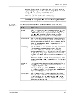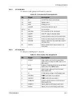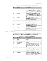
9: Processor Board
PRC1099A-MS
9-13
9.3
Component Locations, Schematics, and Parts List
This section provides a component location diagram, schematic and parts list
for the Processor board.
30
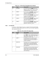
LOWPWR
From the front panel Power switch (S7)
LO
power position. Sets to radio to low RF output
power (5W).
31
CHSWA
From front panel
CHANNEL
switch (S1) for
the A-bit in 4-bit BCD code for channel
selection.
32
CHSWB
From front panel
CHANNEL
switch (S1) for
the B-bit in 4-bit BCD code for channel
selection.
33
CHSWC
From front panel
CHANNEL
switch (S1) for
the C-bit in 4-bit BCD code for channel
selection.
34
CHSWD
From front panel
CHANNEL
switch (S1) for
the D-bit in 4-bit BCD code for channel
selection.
Table 9-6 J5 Connector Pin Assignments (continued)
Pin
Signal
Description


