HOW TO USE X1 - COMMAND BOX SIGNALS TO MARK LAYOUT
PRODUCT REFERENCE GUIDE
97
HOW TO USE X1 - COMMAND BOX SIGNALS TO MARK
LAYOUT
Automate the marking process allowing documents to be marked using external
X1.11
(
START_MARKING
) and
X1.13
(
STOP_MARKING
) signals, which can be generated by PLC
or other external devices.
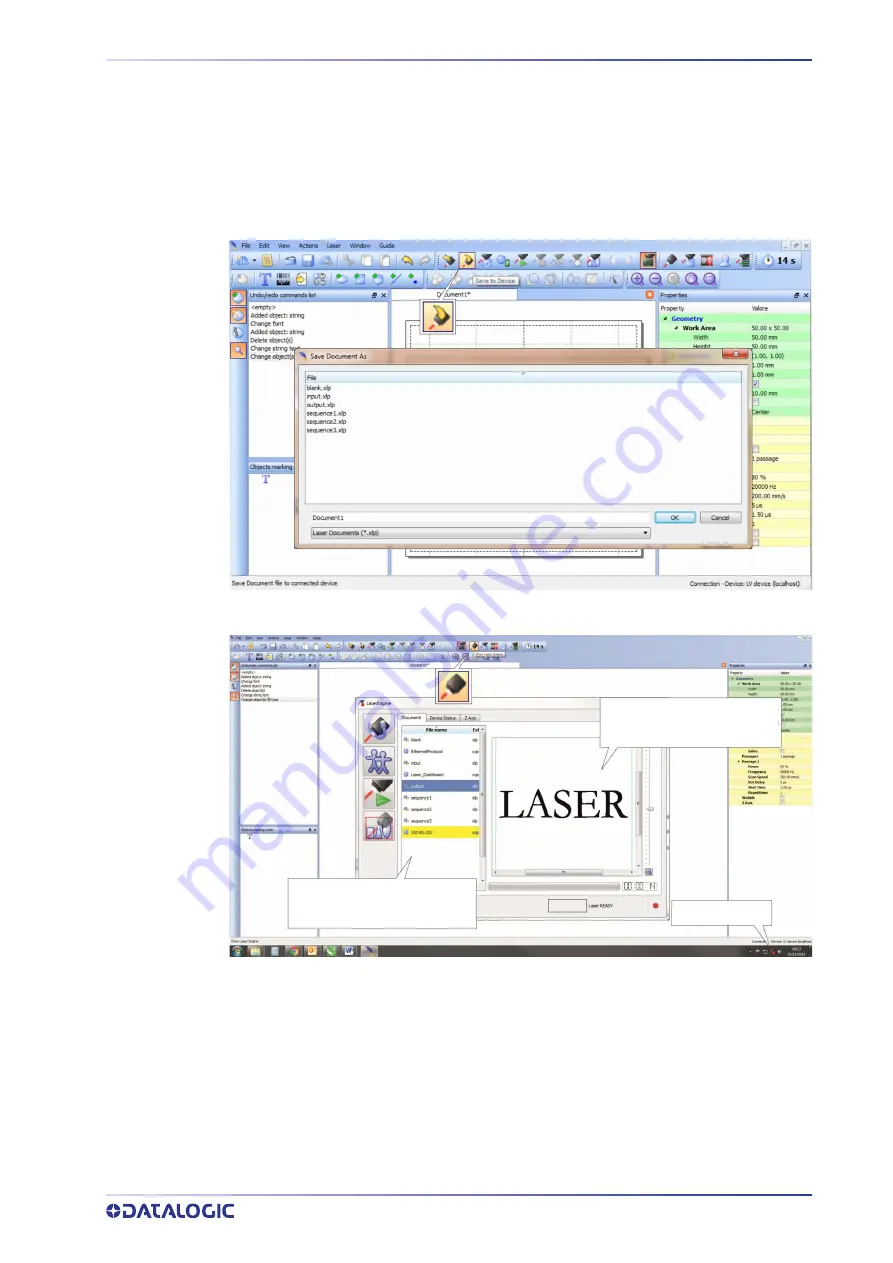
Click on the
Save to Device
button to save the layout in the device memory:
Click on the
Show Laser Engine
button to display Laser Engine window:
Documents tab:
lists all the proj-
ect or documents that have been
saved to the system
Laser marker State
Document preview:
this area
shows how the graphic objects
will be actually marked
AUTO/MANUAL Mode
button allows switching between the two available working
modes:
•
Auto mode: the engraving operations are executed automatically using external
signals.
•
Manual mode: used for displaying the margins of the graphic objects to be marked
and to test layouts.
Summary of Contents for UniQ 1150-1X41
Page 1: ...UniQ PRODUCT REFERENCE GUIDE InfraRed Fiber Laser Marker ...
Page 8: ...PREFACE viii UNIQ ...
Page 82: ...TECHNICAL SUPPORT 74 UNIQ ...
Page 84: ...LABELS 76 UNIQ POSITIONING OF EXTERNAL LABELS Figure 50 External labels location ...
Page 120: ...RECOVER THE LASER MARKER 112 UNIQ 16 Press FINISH to continue 17 Press YES to continue ...
Page 124: ...116 UNIQ APPENDIX G MECHANICAL DRAWINGS ...
Page 126: ...MECHANICAL DRAWINGS 118 UNIQ ...
Page 127: ......


