25-PIN CABLE ELECTRICAL CONNECTIONS
71
5
5.5.3 ID-
NET™ Network Termination
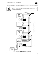
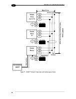
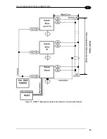
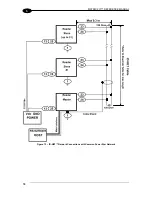
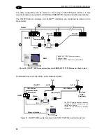
The network must be properly terminated by a 120 Ohm resistor at the first and last reader of
the network.
5.6 AUXILIARY RS232 INTERFACE
The RS232 auxiliary interface is available for Point-to-Point, Pass Through or Master/Slave
connections. When it is connected to the host computer it allows both transmission of code
data and reader configuration by VisiSet™.
The parameters relative to the aux interface (baud rate, data bits, etc.) as well as particular
communication modes such as LOCAL ECHO can be defined through the Communication
folder of the VisiSet™ utility program.
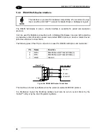
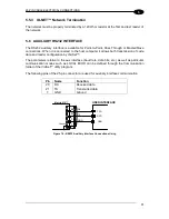
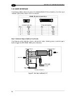
The following pins of the 25-pin connector are used for auxiliary interface communication:
Pin
Name
Function
20
RX
Received data
21
TX
Transmitted data
7
GND
Ground
7
GND
GND
TXD
RX
20
RXD
TX
21
USER INTERFACE
Matrix 210™
1
Chassis
Figure 74 - RS232 Auxiliary Interface Connections Using
Summary of Contents for Matrix 210
Page 1: ...MATRIX 210 Reference Manual...
Page 142: ...www datalogic com...

