MATRIX 210™ REFERENCE MANUAL
56
4
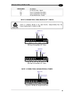
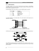
Pulled up to External
Input Device Power
Input
Signal
Input Device
Figure 55 - NPN Input 2 Using External Power
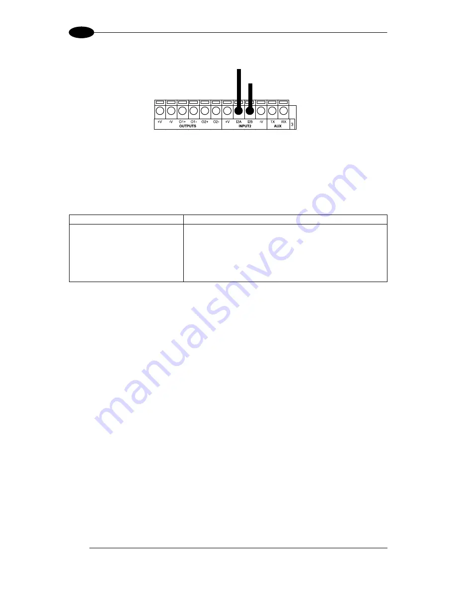
4.6 OUTPUTS
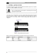
Two optocoupled general purpose outputs are available. The meaning of the two outputs
Output 1 and Output 2 can be defined by the user. They are typically used either to signal the
data collection result or to control an external lighting system.
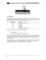
CBX100/500
Function
+V
Power Source - Outputs
O1+
Output 1 +
O1-
Output 1 -
O2+
Output 2 +
O2-
Output 2 -
-V
Power Reference Outputs
The electrical features of the two outputs are the following:
V
CE
= 30 Vdc max.
I
CE
= 40 mA continuous max.; 130 mA pulsed max.
By default, Output 1 is associated with the Partial Read and No Read events, which activates
when the code(s) signaled by the external trigger are not decoded, and Output 2 is
associated with the Complete Read event, which activates when all the selected codes are
correctly decoded.
The output signals are fully programmable being determined by the configured
Activation/Deactivation events, Deactivation Timeout or a combination of the two. Refer to
the Digital I/O folder in the VisiSet™ Help On Line for further details.
Summary of Contents for Matrix 210
Page 1: ...MATRIX 210 Reference Manual...
Page 142: ...www datalogic com...

