DS8110 REFERENCE MANUAL
118
4
Field Name
Action/Definition
Aux (Input 3)
Echo
Select
Disable
or
Enable
from the drop-down list. If enabled, the Scanner Master or
SC5000 Controller
Input 3
status is echoed to the Ethernet Client via bit 2 in Byte
InputBits of the DL_InputStruct.
Phase Echo
This parameter is configurable only if Start Input from Bus is enabled.
Select
Disable
or
Enable
from the drop-down list. If enabled, the
Reading Phase
status is echoed to the Ethernet Client via bit 7 in Byte InputBits of the
DL_InputStruct.
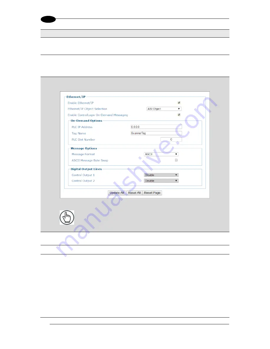
ASI Object: On-Demand Options
NOTE
: Contact Datalogic Support for information on setting up ASI Objects
(legacy Accu-Sort Devices). See Support Through the Website.
PLC IP Address
Enter the IP Address for the PLC Controller (Rockwell Automation: Allen-Bradley
Controllogix or CompactLogix).
Tag Name
Enter a tag name (up to 40 characters) in the field provided.
PLC Slot
Number
Enter the PLC Slot number in the field provided. This corresponds to the physical
slot used on the PLC.
Summary of Contents for DS8110
Page 1: ...REFERENCE MANUAL DS8110 Barcode Scanner ...
Page 40: ...DS8110 REFERENCE MANUAL 28 3 Figure 25 DS8110 Array Tunnel to SC5000 alternate with CBX ...
Page 52: ...DS8110 REFERENCE MANUAL 40 3 Figure 35 OEK 4 95B082050 Encoder Tachometer Wiring NPN Output ...
Page 54: ...DS8110 REFERENCE MANUAL 42 3 Figure 37 OEK 4 95B082050 Encoder Tachometer Wiring PNP Output ...
Page 56: ...DS8110 REFERENCE MANUAL 44 3 3 13 2 Powered Outputs Figure 40 Powered Outputs NPN PNP ...
Page 249: ...BARCODE SCANNING FEATURES 237 5 Figure 69 Reading Diagram DS8110 2100 0 33mm 13mil ...
Page 250: ...DS8110 REFERENCE MANUAL 238 5 Figure 70 Read Chart DS8110 2100 0 38mm 15mil ...
Page 251: ...BARCODE SCANNING FEATURES 239 5 Figure 71 Read Chart DS8110 2100 0 50mm 20mil ...
Page 253: ...BARCODE SCANNING FEATURES 241 5 Figure 73 Reading Diagram DS8110 2200 0 25mm 10mil ...
Page 254: ...DS8110 REFERENCE MANUAL 242 5 Figure 74 Reading Diagram DS8110 2200 0 30mm 12mil ...
Page 255: ...BARCODE SCANNING FEATURES 243 5 Figure 75 Reading Diagram DS8110 2200 0 33mm 13mil ...
Page 256: ...DS8110 REFERENCE MANUAL 244 5 Figure 76 Reading Diagram DS8110 2200 0 38mm 15mil ...
Page 281: ......
Page 282: ......


