TECHNICAL SPECIFICATIONS
19
2
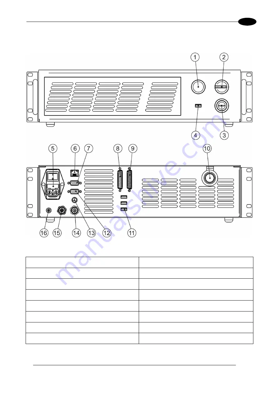
2.2.2 CONTROL RACK
The control rack is described here below in order to provide the right information for proper installation:
Figure 10: Control rack overview.
1) Status LED
9) I/O connector (Axes Control)
2) Enable selector
10) Main connection to Scan Head
3) Key selector
11) 3x USB connectors
4) USB connector
12) RS232 connector
5) Mains power supply connection
13) Interlock connector
6) LAN connector
14) Photocell connector
7) VGA connector
15) Encoder connector
8) Command Box connector (Laser Control)
16) Earth ground
Summary of Contents for Arex 30W
Page 1: ...USER S MANUAL ArexTM 30W 50W ...
Page 92: ...92 APPENDIX G MECHANICAL DRAWINGS ...
Page 93: ...93 NOTE Please refer to Datalogic website for detailed drawings ...
Page 96: ......


