4 Using the Colibrick
Clarity Hardware
added and configured first or, in case of removing one
Colibrick
from the
configuration, for specifying which one is still connected.
Channel 1 (to 4)
For each channel of the
Colibrick A/D Converter
the name of the signal
can be edited in the
Name
field and the
Set Units...
button can be
used to change other signal parameters. Effects of these changes can be
seen in other fields of the respective
Channel 1 (2) section
.
Name
This field will be used to describe the signal in the
window.
Inversion of Signal
Inverts the polarity of the signal from the detector. This function can
also be used for easy correction of inversely connected wires.
Bipolar
Both positive and negative voltages will be measured. Unchecking the
Bipolar
option will improve the resolution of the signal by 1 bit. On the
other hand, it will also restrict the measuring of negative signals (i.e.
below zero).
Set Units...
Invokes the
Detector Units
dialog.
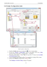
Fig 11: Detector Units
l
Quantity
– Field for entering a name for the y-axis in the graph of the
measured signal.
l
Units
– Field for entering the unit symbol, along with the prefix.
l
Coefficient
– Allows you to enter the coefficient between the selected
units and mV (default).
l
Autoprefix
– Allows you to enter the unit prefix. In graphs, units will be
scaled automatically, while in the tables, units with the prefix entered
will be used.
Synchronize Start with Digital Input
Maps the
Colibrick A/D Converter
channel to selected
External Start
Digital Input
. It enables a faster and more accurate synchronization of
channels with the start signal. Especially for short analyses the necessary
time delays at the start of the acquisition are significant. When measuring
multi- detector chromatograms it will minimize the time shift between
detector signals and thus improve the detection of peaks.
- 14 -

