background image


28 


DCP-24 MKII Digital Cross Over 

Product code: D2083 

7.


Software Operation 

You can adjust the settings of the device with the DSPControl software. The instructions below pertain to 
the firmware version 3.9.0. 

Make sure that the device is connected to the PC or Mac with the installed DSPControl software. 

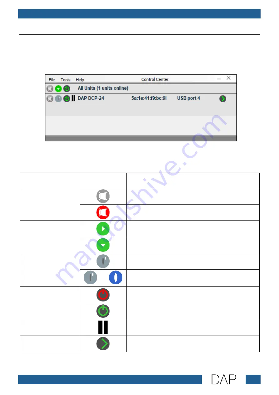
To start the software, double click on the DSPControl.exe file. The main window appears: 


The main window shows all active devices, their MAC addresses and how they are connected to the PC 
or Mac. 

The main window has the following clickable icons: 

Function 

Icon 

Description 

Mute 


Device is not muted. Click to mute the device. 


Device is muted. Click to deactivate mute. 

Fold/Unfold 


Click to unfold the list of devices. 


Click to fold the list of devices. 

Device Indicator 


Click to activate the device. 

 and 


Device is active. 

Status 


Device is off. Click to switch the device on. 


Device is on. Click to switch the device off. 

VU 


VU meter displays the current signal level. 

Arrow 


Click to open the control panel of the selected device. 
See 7.2. Channel Control Panel on page 33. 


Summary of Contents for DCP-24

Page 1: ...DCP 24 MKII Digital Cross Over Highlite International B V Vestastraat 2 6468 EX Kerkrade the Netherlands Product code D2083 USER MANUAL ENGLISH V2...

Page 2: ...f the device Non observance of the instructions in this user manual may result in serious injuries and damage of property 2023 DAP All rights reserved No part of this document may be copied published...

Page 3: ...11 Rack Mounting 11 5 Setup 12 Warnings and Precautions 12 Connecting Devices 12 Setup with Passive Speakers 13 Setup with Active Speakers 14 Connecting to Power Supply 14 Software Installation 15 6 O...

Page 4: ...ar 34 File Tab 34 Edit Tab 34 Hardware Tab 35 Help Tab 35 Channel Control Panel 36 Main Panel 36 In A In B Panels 38 Out 1 4 1 6 Panels 40 8 Troubleshooting 42 9 Maintenance 43 Safety Instructions for...

Page 5: ...ble 1 5 m AC power adapter 6 V 800 mA User manual Fig 01 Intended Use This device is intended for professional use as a digital crossover It is suitable only for indoor installation It is not suitable...

Page 6: ...t in death or serious injury CAUTION Indicates a potentially hazardous situation which if not avoided may result in minor or moderate injury Attention Indicates important information for the correct o...

Page 7: ...livered with an AC power adapter Incorrect handling of the AC power adapter may result in hazardous situations Use only the AC power adapter delivered with the device Do not wrap the power cable aroun...

Page 8: ...n Do not expose the device to conditions that exceed the rated IP class conditions This device is IP20 rated IP Ingress Protection 20 class provides protection against solid objects greater than 12 mm...

Page 9: ...ibution networks You can connect the device to a PC or a Mac and use the DSPControl software Windows MacOS to fine tune your sound system Front View Fig 02 01 Input LED indicator 02 Item up button 03...

Page 10: ...level 0 01 Signal to noise ratio 90 dB Audio latency 1 27 ms DSP processor bitrate 64 bit Frequency response 20 20000 Hz Software Specifications Supported operating systems Windows MacOS Sound editin...

Page 11: ...isplay and jog wheel Control mode Manual PC or Mac software Product properties LED indicators Clip Input level Operation mode Output level Signal Construction Housing Metal Color Black IP rating IP20...

Page 12: ...ive humidity must not exceed 50 with an ambient temperature of 40 C Rack Mounting The device can be mounted in a standard 19 inch rack The device requires 1 rack unit U of space which is 44 5 mm high...

Page 13: ...onnect active speakers see 5 2 2 Setup with Active Speakers on page 14 04 Connect an audio mixer to the 2 x 3 pin XLR balanced connectors IN 15 05 Switch on the audio mixer 06 Switch on the device See...

Page 14: ...the inputs of the 1st amplifier to the 3 pin XLR balanced connectors OUT 1 and 2 12 02 Connect the outputs of the 1st amplifier to the inputs of the 2 passive speakers 03 Connect the inputs of the 2n...

Page 15: ...12 04 Connect the input of the 2nd active subwoofer to the 3 pin XLR balanced connector OUT 4 12 Fig 06 Connecting to Power Supply Attention Incorrect handling of the AC power adapter may result in h...

Page 16: ...load the DSPControl software Check the product page on the website of Highlite International www highlite com To install the DSPControl software on your PC or a Mac follow the steps below 01 Execute t...

Page 17: ...16 DCP 24 MKII Digital Cross Over Product code D2083 04 Select the installation path 05 Click on NEXT...

Page 18: ...k on INSTALL to install the DSPControl on the PC or a Mac When the software is installed you will see the pop up 07 Click on FINISH to finish the installation Note It is recommended to install the Mic...

Page 19: ...view serial number firmware hardware version see 6 2 5 Version Info Routing In this menu you can adjust the routing settings 01 Press the menu button 08 until the display shows 02 Turn the jog wheel...

Page 20: ...ads EMPTY 03 Press the jog wheel 09 to confirm The display shows 04 Turn the jog wheel 09 to the left right to select characters The available characters are uppercase and lowercase letters digits pun...

Page 21: ...display shows 03 Turn the jog wheel 09 to the left right to select characters The available characters are uppercase and lowercase letters digits punctuation marks and some symbols 04 Press the jog wh...

Page 22: ...default password is HIGHLITE Notes When changing the password you can press the item down button 05 to move the cursor to the left press the item up button 02 to move the cursor to the right press the...

Page 23: ...x x x x x x x x STEREO 2 WAY In AB x x x x x x x Out 12 x x x x x x x x x Out 34 x x x x x x x x x MONO 4 WAY In A x x x x x x x In B x x x x x x x Out 1 x x x x x x x x x x Out 2 x x x x x x x x x x...

Page 24: ...dB BES 12 dB LR 12 dB BUT 18 dB BES 18 dB BUT 24 dB BES 24 dB LR 24 dB 04 Press the jog wheel 09 to activate deactivate the filter The display shows 05 Turn the jog wheel 09 to the left right to selec...

Page 25: ...The display shows 03 Turn the jog wheel 09 to the left right to decrease increase the value The adjustment range is from 12 dB to 12 dB 04 Press the jog wheel 09 to open the quality factor settings Th...

Page 26: ...hows 05 Turn the jog wheel 09 to the left right to decrease increase the value The adjustment range is 0 10000 ms 06 Press the jog wheel 09 to open the release settings The display shows 07 Turn the j...

Page 27: ...te value but the level of the signal at 24 dB 12 dB 6 dB or 3dB compared to the threshold of the limiter regardless of the threshold value Link In this menu you can link unlink channels Turn the jog w...

Page 28: ...9 to the left right to decrease increase the delay The adjustment range is 0 9 feet 0 mm 2 74 m and 0 8000 ms Press the jog wheel 09 to toggle the delay measurement unit feet meters milliseconds Phase...

Page 29: ...es their MAC addresses and how they are connected to the PC or Mac The main window has the following clickable icons Function Icon Description Mute Device is not muted Click to mute the device Device...

Page 30: ...u can also quit the software Tools Tab In the TOOLS tab you can set password s for the device s create open groups select the interface language set the DPI of the display enter the demo mode and upda...

Page 31: ...n this menu you can create groups The network compatible speakers can be combined into groups To create a new group name the new group and click on OK The new groups are displayed in the main window a...

Page 32: ...ace for a speaker in the network virtual unit 02 Select a virtual unit you want to add remove 03 Click on add all add selected item remove selected item or remove all to move virtual units to from the...

Page 33: ...ct the scaled DPI display or the high DPI display Enter Demo Mode In this mode you can test the software and create presets without connected speakers Enable Update Enter the password Note If you back...

Page 34: ...33 DCP 24 MKII Digital Cross Over Product code D2083 Channel Control Panel Click on the green arrow icon to open the channel control panel The channel control panel opens...

Page 35: ...unit To copy the settings from one channel to multiple channels follow the steps below 01 Open a channel 02 Adjust the settings of the channel 03 Go to the EDIT tab and click on COPY CHANNEL 04 Open t...

Page 36: ...ssword CONFIGURE In this submenu you can select CHANGE PASSWORD You can change the password POWER ON PRESET You can select a preset that will be loaded on start up GLOBAL ACCESS RIGHTS You can decide...

Page 37: ...ware settings in the memory of the speaker To save a software settings preset 01 Name the preset 02 Select an empty preset slot 1 50 03 Click on the STORE button to save the current software settings...

Page 38: ...the signal phase of all output channels 1 4 or 1 6 when using DCP 26 MKII Click on the button to reverse the signal phase The button lights up red You can set the high pass filter HPF and the low pass...

Page 39: ...meter displaying the current signal level Click on the button to mute the channel The button lights up red You can set the limiter To set the threshold THR and release REL values perform one of the 2...

Page 40: ...range of gain is from 12 dB to 12 dB Select one of the 8 filter types BELL NOTCH HIGH SHELF LOW SHELF ALLPASS BAND PASS HIGH PASS LOW PASS Click on the ON button to activate the filter When active the...

Page 41: ...lider The adjustment range is from 48 dB to 0 dB To mute an input channel type off in the field below a slider The VU meters next to the faders show the input levels for each input Note The mixer does...

Page 42: ...release is 1 100 ms Note Enabling the limiter on a channel changes the way in which the level is displayed on the corresponding output LED indicator 06 The displayed level is no longer the absolute va...

Page 43: ...der the warranty void Such modifications may result in injuries and material damage Refer servicing to instructed or skilled persons Contact your Highlite International dealer in case the solution is...

Page 44: ...sings fixations and installation points The power cables are not damaged and do not show any material fatigue Basic Cleaning Instructions To clean the device follow the steps below Disconnect the devi...

Page 45: ...ectrical and Electronic Equipment This symbol on the product its packaging or documents indicates that the product shall not be treated as household waste Dispose of this product by handing it to the...

Page 46: ...45 DCP 24 MKII Digital Cross Over Product code D2083...

Page 47: ...46 DCP 24 MKII Digital Cross Over Product code D2083...

Page 48: ...2023 DAP...

Reviews: