background image

33

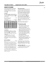
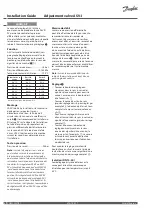
Adjustment valve ASV-I is used together 

with riser valve ASV-P/PV to control 

the differential pressure in risers where 

the radiator valves have no presetting 

facilities 

.

Function

ASV-I gives maximum limitation of water 

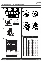
flow (see Setting/adjustment) and the riser 

can be shut off by turning the knob (

❷①

fully clockwise.
Max. working pressure  .......................... 16 bar
Differential pressure  

across valve  ...................................... 10-150 kPa

Max. flow temperature .......................... 120 °C

Valve size

Internal 

thread

External 

thread

DN 15

R

p

 ½

G ¾ A

DN 20

R

p

 ¾

G 1 A

DN 25

R

p

 1

G 1¼ A

DN 32

R

p

 1¼

G 1½ A

DN 40

R

p

 1½

G 1¾ A

DN 50

-

G 2¼ A

Impulse line: G 1⁄16

Installation

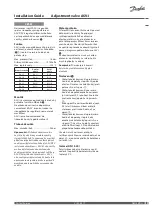
ASV-I must be installed in the riser flow 

pipe. The direction of flow must be from 

port 

B

 to port 

A


. It is recommended 

that an FV filter be installed in the system 

supply pipe.

The impulse line from the riser valve 

must be fitted using an 8 mm open-

ended spanner. ASV-I must in addition 

be installed as determined by installation 

conditions.

Pressure testing

Max. test pressure  ................................... 25 bar

Note:


When pressure testing you must secure 

that both sides of the membrane have the 

same static pressure. That means the impulse 

tube must be connected and any needle 

valves must be open. If ASV-P/PV is installed 

in combination with ASV-M both valves can 

be open or closed (both valves must be in 

the same position!). If ASV-P/PV is installed 

in combination with ASV-I both valves must 

be open. If this instruction is ignored, the 

membrane of the automatic balancing valve 

might be damaged.

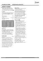
Flow measurement

The differential pressure across the valve 

can be measured by Danfoss measuring 

equipment. When the quick couplings on 

the measuring instrument are connected, 

the test plugss can be opened by giving 

them a half-turn counterclockwise with 

an 8 mm open-ended spanner. The 

pressure loss graph for ASV-I 

 can be 

used to convert the actual differential 

pressure across the valve to actual flow. 

After measurements have been taken, the 

plugs must be closed again by turning 

them clockwise before removing the quick 

couplings.

Note:


When measuring sized flow, all 

radiator valves must be fully open.

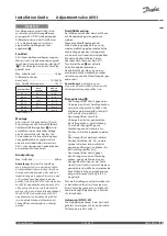
Setting/adjustment 

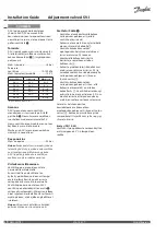
•  Turn the valve knob fully 

counterclockwise to open the valve. 

The mark on the knob will now be 

opposite »0« on the scale 

.

•  Turn the valve knob clockwise to the 

required setting (e.g. for setting 2,2 the 

knob must be rotated two full turns and 

then forward to »2« on the scale 

.

•  Hold the knob to keep the setting (e.g. 

2,2) and using a hexagon socket key 

turn the spindle fully counterclockwise 

(until a stop can be felt), 

.

•  Turn the valve knob fully 

counterclockwise so that the mark 

on the knob is opposite »0« on the 

scale 

. The valve is now open as many 

turns from the closed position (2,2) 

as indicated by the convertion from 

required flow.

To annul the setting, turn the hexagon 

socket key fully clockwise (until a stop can 

be felt), 

. Remember, at the same time 

the knob must be held on its »0« setting.

Insulation (DN 15-40)

The styropor packaging in which the valve 

is supplied can be used as an insulation 

jacket for temperatures up to 80 °C.

Installation Guide 

Adjustment valve ASV-I

District Energy 

VI.A1.K5.1T 

DEN-SMT/SI

ENGLISH

Summary of Contents for ASV-I

Page 1: ... Inregleringsventil ASV I www danfoss com Page 7 SUOMEKSI ASV I www danfoss com Page 8 ČESKY Nastavovací ventil ASV I www danfoss com Page 9 POLSKI Zawór regulacyjny ASV I www danfoss com Page 10 РУССКИЙ Настраиваемый запорно измерительный клапан ASV I www danfoss com Page 11 LIETUVIŲ K Derinimo ventilis ASV I www danfoss com Page 12 ESPAÑOL El ajuste de la válvula ASV I www danfoss com Page 13 RO...

Page 2: ...1 5 68 8 83 1 40 1 05 1 63 2 55 4 08 6 38 9 97 1 60 1 14 1 76 2 84 4 51 7 02 11 01 1 80 1 22 1 88 3 10 4 89 7 60 11 93 2 00 1 30 2 00 3 31 5 20 8 09 12 70 2 20 1 38 2 12 3 44 5 44 8 49 13 30 2 40 1 47 2 24 3 55 5 62 8 79 13 79 2 60 1 53 2 35 3 66 5 78 9 01 14 21 2 80 1 58 2 45 3 78 5 93 9 21 14 64 3 00 1 60 2 50 3 91 6 10 9 49 15 20 3 20 1 60 2 50 4 00 6 30 10 00 16 00 DN 15 2 5 20 3 25 4 32 40 50...

Page 3: ...ht be damaged Flow measurement The differential pressure across the valve can be measured by Danfoss measuring equipment When the quick couplings on the measuring instrument are connected the test plugss can be opened by giving them a half turn counterclockwise with an 8 mm open ended spanner The pressure loss graph for ASV I can be used to convert the actual differential pressure across the valve...

Page 4: ...anen på den automatiske balanceventil ødelægges Måling af flow Differenstrykket over ventilen kan må les med almindeligt måleudstyr Når måleudstyrets lynkoblinger er til sluttet åbnes måleniplerne ved at dreje dem en halv omgang mod uret med en 8 mm fastnøgle Det aktuelle differens tryk over ventilen omsættes til aktuelt flow via tryktabskurven for ASV I Efter endt måling lukkes niplerne igen ved ...

Page 5: ...e Membran des Strangdifferenzdruckreglers beschädigt werden Durchflußmessung Der Differenzdruck über dem Ventil kann mit Standardmeßgeräten gemessen werden Wenn die Schnellkupplungen der Meß einrichtung angeschlossen sind werden die Meßnippel durch eine halbe Umdrehung gegen den Uhrzeigersinn mit einem 8 mm Gabelschlüssel geöffnet Mit dem aktuellen Differenz druck über dem Ventil kann aus der ASV ...

Page 6: ...nne de réglage ASV I ces deux vannes doivent être ouvertes Si ces instructions sont ignorées la membrane du régulateur ASV P ou ASV PV risque d être endommagée Mesure de débit La mesure de pression différentielle peut être effectuée de la façon suivante raccorder les raccords rapides de l instrument de mesure sur les orifices prévus à cet effet et ouvrir les raccords de mesure montés sur la vanne ...

Page 7: ...stning När mätutrustningens snabbkopplingar är anslutna öppnas mätnipplarna genom att vrida dem ett halvt varv moturs med en 8 mm fast nyckel Det aktuella differenstrycket över ventilen räknas om till aktuellt flöde med hjälp av tryckfallskurvan för ASV I Efter avslutad mätning stängs nipplarna och snabbkopplingarna demonteras Observera Vid mätning av dimensione rat flöde ska alla radiatorventiler...

Page 8: ... vastapäivään 8 mm n kiintoavaimella Venttiilin paineero muutetaan ASV I venttiilin painehäviökäyrästön avulla vastaavaksi virtaamaksi Mittausten jälkeen nipat suljetaan kiertämällä niitä vastaavasti myötä päivään minkä jälkeen pikaliittimet irrotetaan Huom Virtausta määritettäessä kaikkien patteriventtiilien on oltava täysin auki Asettelu Säätö Venttiili avataan kääntämällä kahvaa vastapäivään po...

Page 9: ...ci s ASV I oba ventily musí být otevřené Pokud se toto upozornění nerespektuje může se poškodit membrána automatického vyrovnávacího ventilu Měření průtoku Diferenční tlak na ventilu lze měřit pomocí běžně měřící techniky Po připojení rychlopřípojky měřícího zařízení se otevřou měřící vsuky a to otočením o půl otáčky pevným klíčem 8 mm směrem proti hodinám Okamžitý diferenční tlak na ventilu se př...

Page 10: ...a pomiarowego Po podłączeniu sprzętu pomiarowego należy otworzyć końcówki pomiarowe poprzez obrócenie ich o pół obrotu w kierunku przeciwnym do ruchu wskazówek zegara kluczem 8 mm Aktualne ciśnienie różnicowe na zaworze przeliczane jest na aktualny przepływ poprzez wykres spadku ciśnienia dla ASV I Po zakończeniu pomiaru zamyka się końcówki pomiarowe poprzez obrócenie zgodnie z ruchem wskazówek ze...

Page 11: ...крыты Если ASV P PV установлен совместно с ASV I то оба клапана должны быть открыты При невыполнении данных требований мембраны автоматических балансировочных клапанов могут быть разрушены Измерение расхода Потери давления в запорно измерительном клапане могут быть измерены с помощью обычных измерительных приборов После того как быстроразъёмное соединение прибора присоединено к клапану измерительн...

Page 12: ...ss Cuando se conecten los acoplamientos de medida los conectores deben abrirse girándolos media vuelta en sentido contrario a las agujas del reloj con llave de 8 mm Puede utilizarse el gráfico de presión diferencial para convertir en caudal el valor de la presión diferencial Después de haber efectuado las medidas deben cerrarse los conectores girándolos media vuelta en el sentido de las agujas del...

Page 13: ...alima sugadinti automatinio balansavimo ventilio membraną Srauto matavimas Slėgio perkrytį ventilyje galima matuoti Danfoss matavimo įrenginiu Prijungus matavimo jungtį matavimo antgalius galima atidaryti naudojant 8 mm veržliaraktį atviru galu pasukant pusę apsisukimo prieš laikrodžio rodyklę Norint paversti faktinį slėgio perkrytį ventilyje faktiniu slėgiu galima naudoti ASV I slėgio perkryčio g...

Page 14: ...automată a presiunii Măsurarea debitului Presiunea diferenţială în robinet poate fi măsurată cu echipamentele de măsură Danfoss La conectarea racordurilor rapide de pe instrumentul de măsură niplurile de măsurare se pot deschide rotindu le o jumătate de tură la stânga cu o cheie de 8 mm Graficul pierderii de presiune pentru ASV l poate fi utilizat pentru a transforma presiunea diferenţială reală d...

Page 15: ... Se non ci si attiene alle istruzioni la membrana della valvola di bilanciamento automatico potrebbe subire dei danni Misurazione della portata La pressione differenziale nella valvola può essere misurata con uno strumento di misurazione Danfoss Una volta collegati i giunti di accoppiamento rapido i nippli di misurazione possono essere aperti ruotandoli di mezzo giro in senso antiorario con una ch...

Page 16: ...Installation Guide Adjustment valve ASV I 73693430 VI A1 K5 1T Produced by Danfoss A S 11 2014 ...

Reviews: