8
Electrical Installation
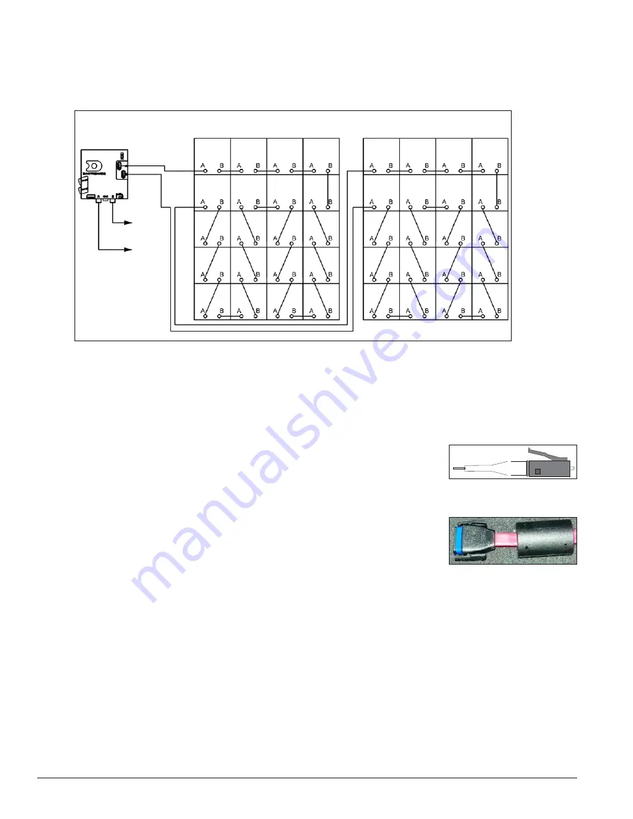
Each PLR sends data to the modules within the display; refer to the contract-specific layout and signal
drawing for further information. Signal exits from the PLR's Fiber Port B jack and routes to Fiber Port A on
the next PLR via fiber-optic cable. Refer to
Figure 10
, as it illustrates a typical signal routing layout. Refer to
the contract-specific Config Drawing for further information.
3.3 Common Connectors
When pulling a connector plug from a jack, do not pull the wire or cable; detach the jack itself. Pulling the
wires may damage the connector. These connectors are not found in every display.
1. Fiber-Optic Connector
LC connectors are square. To remove an LC connector, depress the
small clip on the jack and gently remove. Refer to
Figure 11
.
2. Water-Tight SATA Cable Connector
Daktronics uses a wide variety of SATA cables and SATA cable
connectors.
Figure 12
illustrates one of the most commonly used
connectors. To disconnect the SATA cable connector, squeeze the
locking clips on both sides of the connector inward and pull the plug
out of the jack.
3.4 Control Cable
Reference Drawing:
System Riser Diagram ......................................................................................................
Contract Specific
Refer to the contract specific riser diagram for specifications on signal and power cable runs. The display
controller (DMP-8065 or VIP-5060) reads the video or image signal and feeds the information to the router for
distribution. It processes the video data file. Refer to the
DD2596357
DMP-8065 Quick Guide or
DD2596497
VIP-5060 Quick Guide Street Furniture in
Appendix B
for more information on the controller.
The minimum bend radius for this fiber-optic cable is 15 times the outside diameter of the cable or 7". Refer to
contract specific system riser diagram for the outside diameter of the cable in this system. All fiber-optic runs
must be continuous, except where noted on the System Riser Diagram.
To CTRL
Fiber B
To CTRL
Fiber A
Face A
Front View
Face B
Front View
Figure 10:
Signal Routing
Figure 11:
LC Fiber-Optic
Connector
Figure 12:
SATA Cable
Connector
Summary of Contents for DAKT-0204-02
Page 10: ...6 Cabinet Installation...
Page 28: ...24 Maintenance Troubleshooting...
Page 32: ......
Page 34: ......
Page 36: ......
Page 41: ......
Page 61: ......


