background image

ZX-5

 Ultrasonic Thickness Gauge 

41 


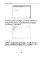
Right click on the CDC device as illustrated above, and select “update driver”.  The 
following window will appear: 


Select “browse my computer” and navigate to the directory where the driver was 
saved on your PC and install the driver.  When the installation is completed, the 
following window will be displayed: 
 

Summary of Contents for Z-303-0001

Page 1: ...OPERATION MANUAL DAKOTA ULTRASONICS Z ZX X 5 5 Ultrasonic Thickness Gauge P N P 303 0002 Rev 1 10 September 2019...

Page 2: ......

Page 3: ...SUREMENT 10 3 1 TIME VERSUS THICKNESS RELATIONSHIP 10 3 2 SUITABILITY OF MATERIALS 10 3 3 RANGE OF MEASUREMENT AND ACCURACY 10 3 4 COUPLANT 10 3 5 TEMPERATURE 11 3 6 MEASUREMENT MODES 11 CHAPTER FOUR...

Page 4: ...UNITS 33 7 7 LITE 33 7 8 ZERO 35 7 9 VELOCITY VX 35 7 10 PROBE DIAMETER 36 7 11 LOCK 37 7 12 FACTORY DEFAULTS 38 CHAPTER EIGHT CONNECTIVITY POWER 40 8 1 CONNECTIVITY 40 8 2 INSTALLING SERIAL DRIVER CD...

Page 5: ...ed in this manual Customer support may be reached at any of the following Dakota Ultrasonics Corporation 1500 Green Hills Road 107 Scotts Valley CA 95066 Tel 831 431 9722 Fax 831 431 9723 www dakotaul...

Page 6: ...TER key similar to a computer keyboard This key will be used to select or set a menu option Note Unit will automatically power off when idle for 5 minutes All current settings are automatically saved...

Page 7: ...ge is 40dB 52dB in 3dB increments Refer to page 28 for details regarding the gain feature 2 5 SCAN Key The ZX 5 offers a high speed scan feature This feature allows for scanning larger areas on a give...

Page 8: ...MENU Navigating the Features in Menu 1 Press the key once to enter the sub menu items 2 Press the keys to toggle through the features 3 To enable or edit the status of any feature press the key 4 The...

Page 9: ...Edit This icon will be displayed and blinking to let a user know when they are in an edit mode to change a value or setting B Large 7 segment The thickness measurement velocity or alpha message will b...

Page 10: ...s in our material list it will be displayed in alpha characters indicating the material type Otherwise it will be set to CUST indicating custom material type L Features The icons illuminated in this r...

Page 11: ...being measured This is accomplished with the use of a coupling fluid commonly called couplant This fluid serves to couple or transfer the ultrasonic sound waves from the transducer into the material a...

Page 12: ...ery cover probe zero disk are located on the ZX 5 s top end cap The transducer connectors are of type Lemo 00 Note There is no polarity associated with connecting the transducer to the ZX 5 it can be...

Page 13: ...i type C female connector It is designed to connect directly from the ZX 5 to a standard USB type A port on a PC The cable supplied with the ZX 5 is a USB type C to a USB type A pt N 003 0330 See page...

Page 14: ...ss measurement is practical in a wide variety of materials including metals plastics and glass Materials that are difficult include some cast materials concrete wood fiberglass and some rubber 3 3 Ran...

Page 15: ...help to minimize these errors 3 6 Measurement Modes This section will cover the different measurements modes of the ZX 5 the transducers required and the reasons for using specific modes Pulse Echo P...

Page 16: ...pending on the material frequency and diameter A limitation of dual element delay line transducers is the V shaped sound path Because the sound travels from one element to another the time versus thic...

Page 17: ...ss are required while still requiring the ability to detect flaws and pits A special coating style transducer is required for use in this mode There are a variety of coating transducers in various fre...

Page 18: ...inherent surface noise issues or mirroring effect Higher frequency transducers 7 10MHz offer improved resolution to avoid erroneous measurements Restricted access Measuring materials with extreme cur...

Page 19: ...to a Known Velocity To determine the velocity of a single sample refer to the Material Calibration section on page 17 When measuring curved materials it s more accurate to calibrate from two test poin...

Page 20: ...n the screen and flashing CLn Prb clean probe 2 Make sure the couplant is wiped clean from the tip of the transducer to avoid any zero error 3 Press the key to perform the zero Performing a Manual Pro...

Page 21: ...bout 0 248 inches per microsecond If the gauge is not set to the correct sound velocity all of the measurements the gauge makes will be erroneous by some amount The One Point calibration is the simple...

Page 22: ...s a one or two point calibration option The one point calibration option is most suited for linearity over large ranges When using the one point option the calibration should be perform on the thickes...

Page 23: ...he keys to scroll to the known thickness value Note The longer the keys are pressed and held the faster the value will increment decrement Note Pressing the key prior to pressing the key will abort th...

Page 24: ...e standard as the probe zero standard For clarification if it s desired to use a one inch reference of a specific material type as the zero reference performing the first point of a two point calibrat...

Page 25: ...o value and returns to the measurement screen Note The internal zero of the ZX 5 is now set The procedure above can be used to set the internal zero of the ZX 5 to use any reference standard as the pr...

Page 26: ...the ZX 5 would offer a reasonable approximation of the thickness There are 9 common materials and 2 user programmable settings available It s important to note that these velocities will not always be...

Page 27: ...prior to pressing the key will abort to the measurement screen without saving any changes 4 If USR1 or USR2 were selected the velocity edit screen will be displayed and edit icon illuminated and flas...

Page 28: ...art and batch within a specified tolerance Using this feature will require calibration on a known thickness that will remain consistent at a specific location on a group of parts The test will always...

Page 29: ...rocedure 1 Physically measure an exact sample of the material or a location directly on the material to be measured using a set of calipers or a digital micrometer 2 Apply a drop of couplant on the tr...

Page 30: ...used to calibrate will be displayed in the top right corner of the display for confirmation 6 3 Calibration to a known velocity The velocity can also be directly edited and set to a target velocity v...

Page 31: ...N s M s value The edit icon will be illuminated and flashing 3 Use the keys to scroll to the known velocity value Note Pressing the key prior to pressing the key will abort the cal routine without sav...

Page 32: ...ications It should be operated in this mode as standard However some applications may require the lower or higher gain settings When The low settings may be necessary for noisy or granular cast materi...

Page 33: ...e ZX 5 increases the overall repetition rate to a maximum of 140Hz with a high speed screen refresh rate of 25 times a second This allows for making scanned passes over an arbitrary length of the test...

Page 34: ...keys to scroll through the items features until the ALRM feature is being displayed 3 Press the key to edit the alarm status The edit icon will be illuminated and flashing 4 Use the keys to toggle al...

Page 35: ...and measure the difference from the nominal value entered This feature is typically used in QA incoming inspections on pipes plate stock coils etc The steps below outline how to enable and enter the n...

Page 36: ...sed with the alarm feature for the key strokes on the keypad When enabled pressing any of the keys on the keypad will sound the beeper The procedure to enable the keyboard beeper feature is outlined b...

Page 37: ...s features until the UNIT feature is being displayed 3 Press the key to edit the units setting The edit icon will be illuminated and flashing 4 Use the keys to toggle English or Metric units Note Pres...

Page 38: ...ll be illuminated and flashing 4 Use the keys to toggle status on off auto Note Pressing the key prior to pressing the key will abort to the measurement screen without saving changes 5 When the desire...

Page 39: ...ption only is outlined below Zero Auto Manual 1 Press the key to access the menu items features 2 Use the keys to scroll through the items features until the ZERO feature is being displayed 3 Press th...

Page 40: ...terial at a given position on the test material Refer to the making measurements section on page 24 for a complete explanation of the zero and one point calibration procedure The procedure to enable t...

Page 41: ...eter is outlined below Probe 1 Press the key to access the menu items features 2 Use the keys to scroll through the items features until the PROB feature is being displayed 3 Press the key to edit the...

Page 42: ...the ZX 5 on The lock icon will be illuminated on the display 2 To unlock the ZX 5 repeat step one but hold down the key while powering the ZX 5 on 7 12 Factory Defaults The ZX 5 can be reset to factor...

Page 43: ...e of the MEDI ZERO settings prior to performing a reset These values will need to be entered back in the gauge following the reset 4 Press the keys to scroll REST reset 5 Press the key to edit the res...

Page 44: ...on the PC board of the ZX 5 Refer to our price list for additional information on communication module options and cables 8 2 Installing Serial Driver CDC When the ZX 5 is powered on and connected to...

Page 45: ...illustrated above and select update driver The following window will appear Select browse my computer and navigate to the directory where the driver was saved on your PC and install the driver When t...

Page 46: ...ations capability can be used to connect to the ZX 6 and will capture the measurements to your PC when the ENTER key is pressed 8 3 Line Power The ZX 5 can be powered using the standard USB C to USB A...

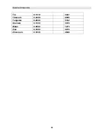
Page 47: ...0 1280 3251 Inconel 0 2290 5817 Iron 0 2320 5893 Cast Iron 0 1800 approx 4572 Lead 0 0850 2159 Magnesium 0 2300 5842 Mercury 0 0570 1448 Molybdenum 0 2460 6248 Monel 0 2110 5359 Nickel 0 2220 5639 Nyl...

Page 48: ...Dakota Ultrasonics 44 Tin 0 1310 3327 Titanium 0 2400 6096 Tungsten 0 2040 5182 Uranium 0 1330 3378 Water 0 0580 1473 Zinc 0 1660 4216 Zirconium 0 1830 4648...

Page 49: ...st be observed At temperatures above this point the change in sound velocity of the material being measured starts to have a noticeable effect upon ultrasonic measurement At such elevated temperatures...

Page 50: ...mize error is another option An additional important consideration when measuring laminates is that many included air gaps or pockets which will cause an early reflection of the ultrasound beam This e...

Page 51: ...h respect to this product Dakota Ultrasonics specifically disclaims any implied warranties of merchantability or fitness for a particular purpose Some states or provinces do not allow limitations on t...

Reviews: