background image

GARO AB

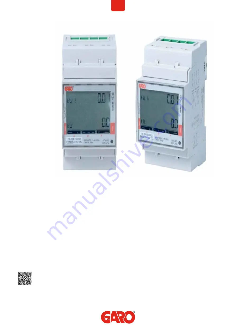
GARO GNM3T-RS485 as DLM meter

Box 203, SE–335 25 Gnosjö
[email protected]

garo.se

Manual 380255

DLM = Dynamic Loadbalancing Meter

Installation and Programming Manual (EN)

Summary of Contents for GNM3T-RS485

Page 1: ...GARO AB GARO GNM3T RS485 as DLM meter Box 203 SE 335 25 Gnosjö info garo se garo se Manual 380255 DLM Dynamic Loadbalancing Meter Installation and Programming Manual EN ...

Page 2: ...io settings 5 System setting 6 System options 6 CT Ratio setting 7 UT Ratio setting 8 Confirm System CT and UT Ratio settings 9 Verify System CT and UT Ratio settings 9 Final confirmation of System CT and UT Ratio settings 10 Modbus settings 10 Modbus address information 12 Set the Modbus Adress 13 Set verify the Baudrate 14 Set verify the Parity and stopbit 14 Confirm settings 15 ...

Page 3: ...eeded Warnings Make sure the electrical power is off before start of installation process All electrical installation must be performed by an auhorized electrician MODBUS CONNECTION Install the DLM meter in the mains cabinet you want to monitor Use shielded twisted pair cable between the DLM meter and the wallbox Suitable cables CAT5 FTP CAT5e FTP CAT6 FTP ELAKY S ELAQBY S or similar 3 EN 10 T 12 ...

Page 4: ...L CONNECTION POWER CABLES N 1 2 3 section 4 mm torque 0 6 Nm 4 17 section 1 5 mm torque 0 4 Nm EN 4 L N F 16 17 Rx L1 L2 L3 N F N 1 2 8 4 7 9 3 5 6 L1 L2 N F N 1 2 4 7 5 6 L1 L2 L3 F 1 2 8 4 7 9 3 5 6 3Pn 2P 3P ...

Page 5: ... Touch area Note Can only be performed once System and CT Ratio settings 1 This view is shown as startup view before the System and CT ratio settings are done When the System and CT ratio settings are done this view is not visible again ...

Page 6: ...ress center touch area to confirm and no is visible Rx 2 Rx 3 Click right touch area to change to YES 4 Press center touch area to confirm the setting 1P 1phase N 2P 2phase N 3 wire 3P 3phase 3 wire 3Pn 3phase N 4 wire Rx Rx EN 6 System setting System options ...

Page 7: ...Repeat until the complete value is correct and no is visible Rx Rx 3 Click right touch area to change to YES 4 Press center touch area to confirm the setting Rx 7 EN CT Ratio setting CT Ratio values depending on the CT you use 100 5A CT Ratio 20 150 5A CT Ratio 30 250 5A CT Ratio 50 400 5A CT Ratio 80 750 5A CT Ratio 150 800 5A CT Ratio 160 1250 5A CT Ratio 250 1600 5A CT Ratio 320 ...

Page 8: ...isible Confirm by press center touch area and next figure starts to blink Repeat until the complete value is correct and no is visible Rx NOTE Correct Ut Ratio value is 1 for 230 400V systems Rx 3 Click right touch area to change to YES 4 Press center touch area to confirm the setting Rx UT Ratio setting EN 8 ...

Page 9: ...irm the setting 6 Verify System CT and UT Ratio settings If the settings are incorrect you can at this stage by pressing center touch area start the setting process again at step 2 no must be visible The settings for System CT and UT Ratio is visible step by step Verify that all values are correct When all settings are correct go to step 7 ...

Page 10: ...of System CT and UT Ratio settings 1 Click right touch area to change to YES 2 Press center touch area to confirm 3 System CT and UT Ratio settings are now done Main menu is visible 8 Modbus settings Longpress center touch area until you see PASS ...

Page 11: ...11 EN Rx Rx Rx 10 Longpress center touch area until you see PASS 9 Longpress both left and right touch area side to bypass the password The blinking 0 will stop to blink after 2 seconds ...

Page 12: ... a grid use address 100 DLM settings in the webinterface are required Address 100 require an installed wifi module in the Master Wallbox Note When use of Adress 100 the wallbox will not paus the charging process if available current is below 6A If you want to monitor a 2nd mains cabinets a 2nd DLM meter can be installed in the 2nd mains cabinet The modbus address for the 2nd DLM meter should be 10...

Page 13: ...o blink 2 Click left or right touch area to modify the figure 3 Longpress center touch area to change to next figure and repeat step 2 Rx Rx 4 When the adress is correct longpress center touch area to confirm the address Rx Set the Modbus Adress 13 EN ...

Page 14: ...ongpress center touch area Rx NOTE Correct Value Baudrate 9 6 Rx 1 Click left touch area until PArIty is visible Default is no and this is correct If you need to change the parity longpress center touch area and click left or right touch area until no is visible Confirm by longpress center touch area Rx Set verify the Baudrate 14 Set verify the Parity and stopbit NOTE Correct Values Parity no Stop...

Page 15: ...5 Confirm settings 1 Click left touch area until End is visible 2 Longpress center touch area when End is visible and the setting is confirmed 3 The square is blinking when DLM meter have communication with the wallbox ...

Reviews: