Unit Startup and Maintenance
www.DaikinApplied.com 69
IOM 1274-3 • CENTRIFUGAL WATER CHILLERS
back into operation after it has been opened for service, as
recommended from previous sample results or after a failure.
The presence of residual materials from a failure should be
taken into consideration in subsequent analysis. While the unit
is in operation, the sample should be taken from a stream of
refrigerant oil, not in a low spot / quiet area.
Table 32: Upper Limit For Wear Metals And Moisture In
Polyolester Lubricants
Element
Upper Limit (PPM)
Action
Aluminum
50
1
Copper
100
1
Iron
100
1
Moisture
150
2&3
Silica
50
1
Total Acid Number (TAN)
0.19
3
Corresponding Action:
1. Re-sample after 500 hours of unit operation. If content
increases less than 10%, change oil and filter and re-
sample at normal interval. If content increases between
11% and 24%, change oil and oil filter and re-sample
after an additional 500 hours of operation. If content
increases 25% or more, inspect compressor.
2. Re-sample after 500 hours of unit operation. If content
increases less than 10%, change filter drier and re-
sample at normal interval. If content increases between
11% and 24%, change filter-drier and re-sample after an
additional 500 hours of operation. If content increases
25% or more, monitor for water leak. Since POE
lubricants are hygroscopic, many times the high moisture
level is due to inadequate handling and packaging.
The TAN reading
MUST BE USED
in conjunction with
moisture readings.
3. For TAN between .10 and .19, re-sample after 1000
hours of unit operation. If TAN increases above 19,
change oil, oil filter and filter drier and re-sample at
normal interval.
Flow Switch Installation and Calibration
A thermal dispersion flow switch uses heat to determine
flow and therefore must be calibrated during system startup.
A thermal dispersion flow switch can be an acceptable
replacement for paddle type flow switches and differential
pressure switches but care must be taken regarding wiring.
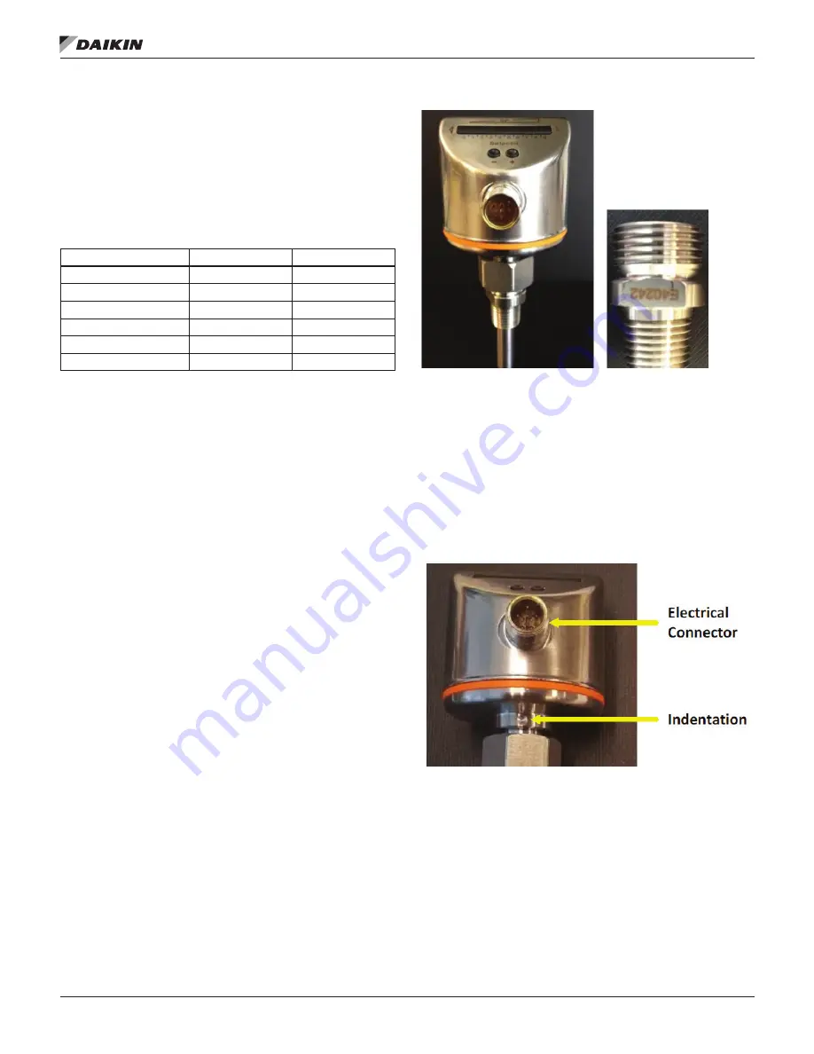
The thermal dispersion flow switch supplied by Daikin Applied,
shown in Figure 1, comes as a 2 part unit consisting of a flow
switch and an adapter labeled E40242 by the supplier.
Figure 75: Thermal Dispersion Flow Switch and Adapter
Mounting
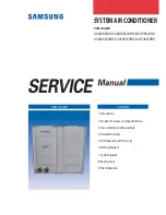
Figure 76
highlights the position of the electrical connector and
indentation ‘mark’ on flow switch.
It is required that the flow switch be mounted such that the
electrical connection and indentation ‘mark’ are oriented as
recommended in
Figure 77
. It is important that the flow switch
be mounted so that the probe is sufficiently inserted into the
fluid stream. It may not be mounted directly on top or directly
on the bottom of a horizontal pipe.
Figure 76: Flow Switch Details
If the flow sensor is to be mounted away from the unit, the
sensor should be mounted on the wall of the inlet pipe of
evaporator and condenser, or in a run of straight pipe that
allows 5 to 10 pipe diameters prior to the sensor and 3 to 5
pipe diameters of straight pipe after the sensor. Flow switch
is placed in inlet pipe to reflect flow entering the barrel. If
installation on the outlet pipe is necessary, contact Chiller
Technical Response at [email protected] to
review the jobsite details.
NOTE:
DO NOT alter or relocate factory installed flow switch.
If issues exist, contact Chiller Technical Response at
IMPORTANT
: Flow switch
MUST be calibrated before
chiller operation. Failure to
properly calibrate the switch
may result in severe chiller
damage and/or void warranty.


