


Installation manual
10
RXYSQ4~6M7V3B
VRVII-S system air conditioner
4PW17806-1C
9.7.
Leak test and vacuum drying
The units were checked for leaks by the manufacturer.
See
"Additional refrigerant charge" on page 10
for nomenclature of the parts in figure 6.
• Confirm that the gas and liquid line stop valves are firmly closed
before pressure test or vacuuming.
• Make sure that valve A is completely open.
Air tight test and vacuum drying
■
Air tight test: Make sure to use nitrogen gas. (For the service
port position, refer to
"9.2. Cautions for handling stop valve" on
■
Pressurize the liquid and gas pipes to 3.8 MPa (38 bar) (do not
pressurize more than 3.8 MPa (38 bar)). If the pressure does not
drop within 24 hours, the system passes the test. If the pressure
drops, check where the nitrogen leaks from.
■
Vacuum drying: Use a vacuum pump which can evacuate to
–100.7 kPa (5 Torr, –755 mm Hg)
1.
Evacuate the system from the liquid and gas pipes by using a
vacuum pump for more than 2 hours and bring the system to
–100.7 kPa. After keeping the system under that condition for
more than 1 hour, check if the vacuum gauge rises or not. If it
rises, the system may either contain moisture inside or have
leaks.
2.
Following should be executed if there is a possibility of moisture
remaining inside the pipe (if piping work is carried out during the
raining season or over a long period of time, rainwater may enter
the pipe during work).
After evacuating the system for 2 hours, pressurize the system to
0.05 MPa (vacuum break) with nitrogen gas and evacuate the
system again using the vacuum pump for 1 hour to –100.7 kPa
(vacuum drying). If the system cannot be evacuated to –100.7 kPa
within 2 hours, repeat the operation of vacuum break and vacuum
drying.
Then, after leaving the system in vacuum for 1 hour, confirm that
the vacuum gauge does not rise.
9.8.
Additional refrigerant charge
See
To avoid compressor breakdown. Do not charge the refrigerant
more than the specified amount.
■
This outdoor unit is factory charged with refrigerant and
depending on pipe sizes and pipe lengths some systems require
additional charging of refrigerant. See
additional refrigerant to be charged" on page 9
■
Make sure to use installation tools you exclusively use on
R-410A installations to withstand the pressure and to prevent
foreign materials from mixing into the system.
■
Charge the refrigerant to the liquid pipe in its liquid state. Since
R-410A is a mixed refrigerant, its composition changes if
charged in a state of gas and normal system operation would no
longer be assured.
■
Before filling, check whether the tank has a siphon attached or
not.
■
Determine the weight of refrigerant to be charged additionally
referring to the item "Additional refrigerant charge" in
calculate the additional refrigerant to be charged" on page 9
and fill in the amount in the "Additional refrigerant charge label"
attached to the unit.
Charging while the outdoor unit is at standstill
■
After the vacuum drying is finished, charge the additional
refrigerant in its liquid state through the liquid stop valve service
port taking into account following instructions:
-
Check that gas and liquid stop valves are closed.
-
Stop the compressor and charge the specified weight of
refrigerant.
Charging while the outdoor unit is operating
1
Completely open the gas line stop valve.
Valve A must be left fully closed. Make sure the liquid stop valve
is totally shut. If it is open, the refrigerant cannot be charged.
Charge the additional refrigerant in its liquid state through the
service port of the liquid line stop valve.
2
While the unit is at standstill and under setting mode 2 (refer to
Checks before initial start-up
set the required function A (additional refrigerant charging
operation) to
(ON). Then operation starts. The blinking H2P
led indicates test operation and the remote controller indicates
(test operation) and
(external control).
3
When the specified amount of refrigerant is charged, push the
button. Then operation stops.
■
The operation automatically stops within 30 minutes.
■
If the refrigerant charge cannot be finished within 30 minutes,
repeat step 2.
■
If the operation stops immediately after restart, there is a
possibility that the system is overcharged.
The refrigerant cannot be charged more than this amount.
4
After the refrigerant charge hose is removed, make sure to fully
open the liquid stop valve. Otherwise the piping may burst due to
blocked liquid.
5
After the refrigerant is charged, turn on the power for the indoor
units and for the outdoor unit.
Refrigerant cannot be charged until field wiring has been
completed.
Refrigerant may only be charged after performing the leak
test and the vacuum drying (see above).
When charging a system, care shall be taken that its
maximum permissible charge is never exceeded, in view of
the danger of liquid hammer.
Charging with an unsuitable substance may cause
explosions and accidents, so always ensure that the
appropriate refrigerant (R-410A) is charged.
Refrigerant containers shall be opened slowly.
Always use protective gloves and protect your eyes when
charging refrigerant.
1
Presssure reducing valve
2
Nitrogen
3
Tank
4
Siphon system
5
Measuring instrument
6
Vacuum pomp
7
Valve A
8
Gas line stop valve
9
Outdoor unit
10
Liquid line stop valve
11
Indoor unit
12
Stop valve service port
13
Charge hose
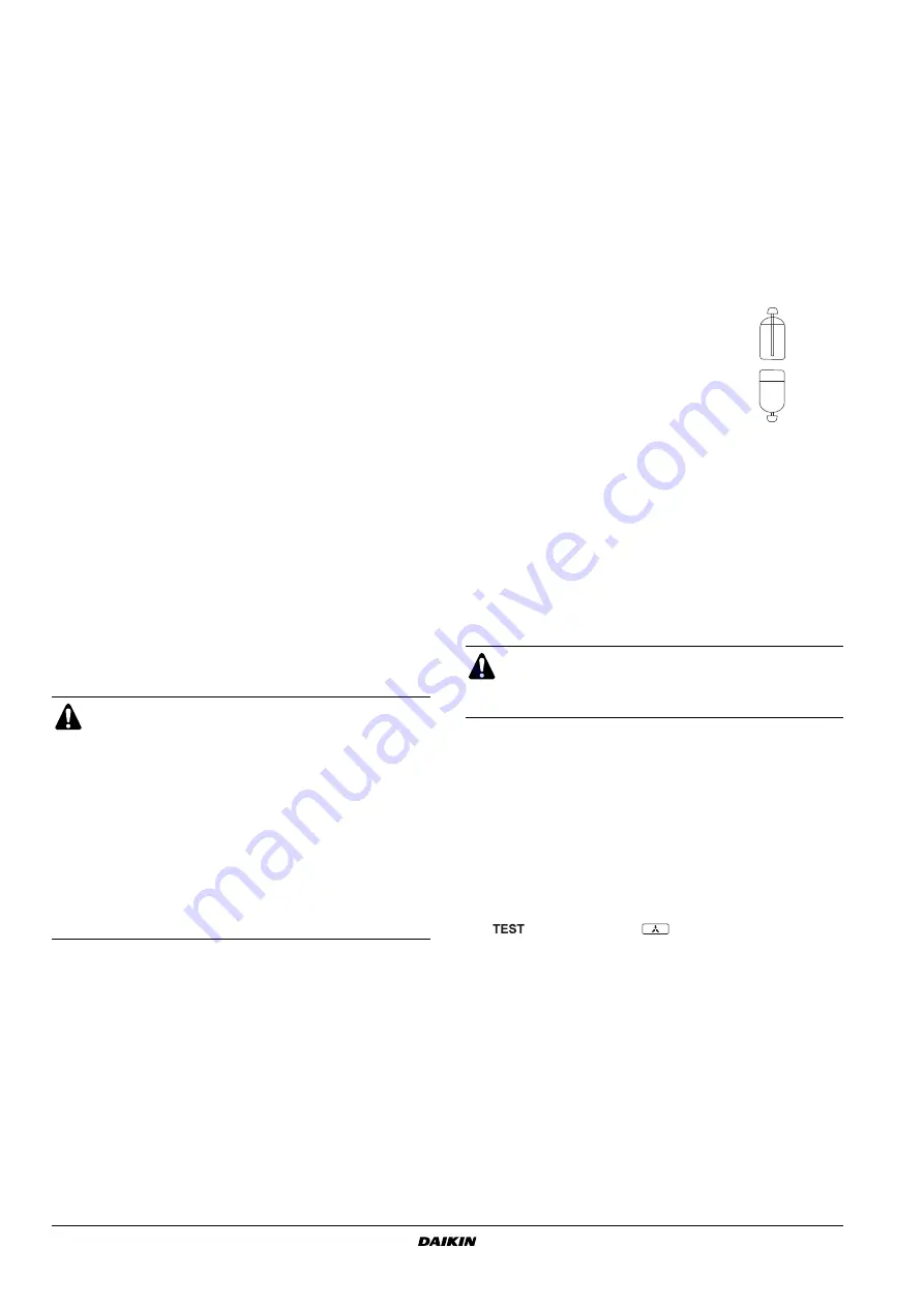
How to fill a tank with a siphon attached
Fill with the tank upright.
There is a siphon tube inside, so there is no
need to turn the tank upside-down.
Other ways of filling the tank
Fill with the tank upside-down.
If the total refrigerant cannot be charged while the outdoor
unit is at standstill, it is possible to charge the refrigerant by
operating the outdoor unit using the refrigerant charge
function (refer to
).
ON
BS3 RETURN


