background image

English

14

Note

For wiring, use the designated power wire and connect firmly, 
then secure to prevent outside pressure being exerted on the ter-
minal board.

Be sure to use crimp-style terminal with insulating sleeves for 
connections. (See the figure below.)

When pulling the ground wire out, wire it so that it comes through 
the cut out section of the cup washer. (See the figure below.) An 
improper ground connection may prevent a good ground from 
being achieved.

When two wires are connected to a single terminal, connect them 
so that the rear sides of the crimp contacts face each other. Also, 
make sure the thinner wire is on top, securing the two wires simul-
taneously to the resin hook using the included clamp (1).

Use an appropriate screwdriver for tightening the terminal screws. 
A screwdriver with a small head will strip the head and make 
proper tightening impossible.
Over-tightening the terminal screws may break them.
See the following table for the tightening torque of the terminal 
screws.

7-6 Procedure for Wiring Inside Units

Referring to figure 27 and 28, secure and wire the power and 
transmission wiring using the included clamp (1), (2), and (3).

Wire so that the ground wiring does not come into contact with the 
compressor lead wiring.
If they touch, this may have an adverse effect on other devices.

Make sure all wiring do not contact to the pipes (hatching parts in 
the figure 27 and 28).

The transmission wiring must be at least 50 mm away from the 
power wiring.

(Refer to figure 27)

1.

For RTSQ8 to RTSQ12PY1

2.

For RTSQ14 and RTSQ16PY1

3.

In the case of pulling in the power wire and ground wire 
from the left-hand side.

4.

Conduit

5.

Stay

6.

Fix to the stay with the included clamp (3).

7.

Power wiring

8.

Ground wiring

9.

Transmission wiring

10.

In the case of pulling in the power wire and ground wire 
from the right-hand side.

11.

In the case of pulling in the transmission wire from the 
piping outlet.

12.

In the case of pulling in the power wiring and ground wir-
ing from the front side.

13.

Separate at least 50 mm.

14.

In the case of pulling in the transmission wiring from the 
front side.

15.

Fix to the rear side of the side plate with the included clamp (2).

16.

Support

17.

Fix to the rear side of the support with the included clamp (1).

18.

Fix to the rear side of the support with the included clamp (2).

19.

Perform wiring carefully so that the sound blanket of the 
compressor will not be dismounted.

(Refer to figure 28)

1.

For BTSQ20PY1

2.

Power wiring

3.

Ground wiring

4.

Transmission wiring

5.

In the case of pulling in the power wiring and ground wir-
ing from the left-hand side.

6.

In the case of pulling in the power wiring and ground wir-
ing from the right-hand side.

7.

Pull in the transmission wiring from the piping outlet.

8.

Perform wiring (on both right- and left-hand sides) so that 
the sealing materials on the bottom of the 
EL.COMPO.BOX will not be deformed.

9.

Perform wiring carefully so that the sound blanket of the 
compressor will not be dismounted.

Note

After wiring work is completed, check to make sure there are no 
loose connections among the electrical parts in the 
EL.COMPO.BOX.

8.

TESTS AND INSULATION WORK

Note

Always use nitrogen gas for the airtightness test.

Absolutely do not open the shutoff valve until the main power ciruit 
insulation measurement (refer to 8-3) has been completed. (mea-
suring after the shutoff valve is opened will cause the insulation 
value to drop.)

8-1 Air tight test and vacuum drying

 After finished piping work, carry out air tight test and vacuum drying.

Note

Be sure to conduct the airtight test and vacuum drying through the 
service port of the shutoff valves of the liquid pipe and gas pipe, 
and shutoff valve of the equalizer pipe (for the multi outdoor unit 
system only) of the outdoor unit and the service port of the liquid 
pipe and gas pipe of the function unit.
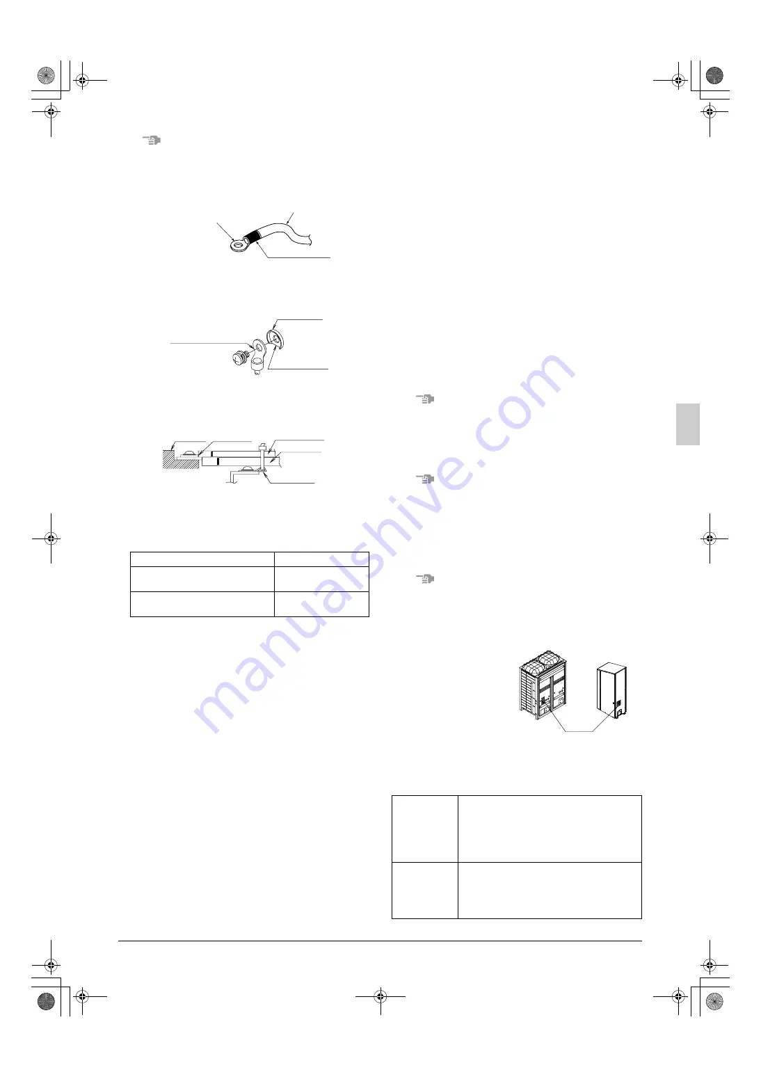
See the [R410A] Label 
attached to the front plate of 
the each unit for details on 
the location of the service 
port (see figure at right).

See 

[Shutoff valve opera-

tion procedure] 

in “

9-1 

Before working

” for details 

on handling the shutoff valve.

Pay attention to refrigerant 
leakage when connecting a 
charge hose to the refrigerant charge port. The refrigerant charge 
port is connected to the piping inside the product, and the piping 
is charged with refrigerant before shipping from the factory.

<Needed tools>

Screw size

Tightening torque (N·m)

M8 (Power and ground terminals of 

outdoor unit)

5.5 - 7.3

M5 (Power and ground terminals of 

outdoor unit)

2.0 - 3.0

Power wire

Crimp-style terminal

Insulating sleeve

Crimp-style terminal

Cup washer

Cut out section 

Terminal 
block

Crip style 
terminal

Wire : narrow

Wire : thick

Resin hook

Gauge manifold
Charge hose 
valve

• To prevent entry of any impurities and insure 

sufficient pressure resistance, always use the 
special tools dedicated for R410A.

• Use charge hose that have pushing stick for 

connecting to service port of shutoff valves or 
refrigerant charge port.

Vacuum pump

• Take care the pump oil never flow backward 

into the refrigerant pipe during the pump stops.

• The vacuum pump for vacuum drying should 

be able to lower the pressure to –100.7kPa 
(5 Torr –755mm Hg).

[R410A] Label

Outdoor unit

Function unit

01_EN_3P201178-10P.fm  Page 14  Wednesday, September 2, 2009  11:10 AM

Summary of Contents for RTSQ10PY1

Page 1: ...nglish Norsk Svenska Deutsch Fran ais Polski Installation manual VRVIII C System air conditioner Installationsanleitung VRVIII C System Klimaanlage Manuel d installation Conditionneur d air VRVIII C S...

Page 2: ...PY1 RTSYQ16PY1 RTSYQ20PY1 RTSQ8PY1 RTSQ10PY1 RTSQ12PY1 RTSQ14PY1 RTSQ16PY1 BTSQ20PY1 REYQ8PY1 REYQ10PY1 REYQ12PY1 REYQ14PY1 REYQ16PY1 REYQ18PY1 REYQ20PY1 REYQ22PY1 REYQ24PY1 REYQ26PY1 REYQ28PY1 REYQ30...

Page 3: ...0 300 500 10 50 100 10 100 300 300 500 50 200 200 400 200 200 50 100 10 100 500 50 50 100 50 100 1 3 6 6 6 2 7 6 6 6 9 8 9 8 9 8 9 8 3 4 5 4 5 2 unit mm 1 2 5 4 3 figure 7 727 765 300 460 1 1 2 8 8 5...

Page 4: ...re 11 6 3 4 5 2 8 7 9 10 1 2 4 3 2 1 figure 12 1 3 5 11 11 11 11 9 12 12 13 13 7 10 9 10 4 7 3 6 11 11 11 11 11 11 9 9 8 8 10 10 2 figure 15 figure 21 9 7 8 10 2 3 12 13 7 15 17 18 15 16 14 1 11 4 5 6...

Page 5: ...10 9 1 8 5 7 9 6 4 3 2 figure 26 1 3 2 2 1 3 4 5 6 7 1 10 8 9 figure 30 figure 31 2 3 13 7 8 9 10 12 11 16 6 5 4 14 15 1 17 18 19 20 figure 34 figure 29 figure 23 1 2 F1 F2 F1 F2 F1 F2 F1 F2 F1 F2 1...

Page 6: ...leakage electric shocks or fire Install the air conditioner in accordance with the instructions in this installation manual Improper installation may result in water leakage electric shocks or fire Wh...

Page 7: ...quired additional refrig erant must be charged in its liquid state If the system is charged with refrigerant in its gaseous state due to composition change the system will not function normally Limit...

Page 8: ...both units Do not throw away any of the accessories until installation is com plete They are needed for installation work Request the user to keep the explanation documents after the installation work...

Page 9: ...power wiring and transmission wiring in conduits and ground the conduits Refer to figure 3 1 Indoor unit 2 Branch switch overcurrent breaker 3 Remote controller 4 Personal computer or radio 5 Air outl...

Page 10: ...intless phosphor deoxidized copper pipe Size See 6 5 Example of connection to determine the cor rect size Thickness Select a thickness for the refrigerant piping which complies with national and local...

Page 11: ...tract the gas in the pinch piping 4 Step 2 After the gas is extracted melt the blazing mate rial with a burner and remove the pinch pipes 3 Connecting refrigerant piping to outdoor units and function...

Page 12: ...int horizontally so that the attached warning label faces strait up and the tilt is within 15 Refer to figure 17 1 Do not install vertically Refer to figure 17 2 Maintain a straight portion of 500 mm...

Page 13: ...Horizontal surface 2 B arrow view Oil remains in the stopping outdoor unit Rising height 200 mm or more 1 Connect straightly 2 Put rising Prohibited pattern Front connection Bottom connection To indoo...

Page 14: ...nd outdoor units Between outdoor unit and function unit Actual pipe length Equivalent length Actual and Equivalent pipe length Difference in height Difference in height Difference in height Difference...

Page 15: ...s the requirements of Japanease High Pressure Gas Controll low As of Jan 2003 The thickness and material shall be selected in accordance with local code In case of single outdoor unit system In case o...

Page 16: ...at 19 1 Total length m of liquid piping size at 12 7 Total length m of liquid piping size at 6 4 0 37 0 18 0 059 0 26 0 12 0 022 FOR THE SYSTEM SYSTEM NAME THE AMOUNT OF REFRIGERANT Example for refri...

Page 17: ...and an malfunction code will be displayed on the indoor remote controller Never remove thermistor sensor or etc when connecting power wiring and transmission wiring If operated with thermistor sensor...

Page 18: ...board Attach with care See the table below for the tightening torque of the transmission wiring terminals All transmission wiring should use sheathed vinyl cord 0 75 1 25 mm2 or cable duplex Transmiss...

Page 19: ...ing in the power wiring and ground wir ing from the left hand side 6 In the case of pulling in the power wiring and ground wir ing from the right hand side 7 Pull in the transmission wiring from the p...

Page 20: ...rogen gas then depressurize down to 100 7 kPa for an hour using the vacuum pump vacuum drying 2 If the pressure does not reach 100 7 kPa even after depressur izing for at least two hours repeat the va...

Page 21: ...the refrigerant charging operation close the valve of the refrigerant tank immediately The refrigerant charge port of this product have electric expan sion valve The valve will be closed at end of ref...

Page 22: ...cts the main body seal 3 Make sure to tighten the cap securely For the tightening torque refer to the item Tightening Torque 8HP type 10HP type 12HP type 14HP type 16HP type Liquid pipe shutoff valve...

Page 23: ...refrigerant amount in the field and total refrig erant amount of the system to Refrigerant charge label and adhere in the proximity of the refrigerant charge port About Refrigerant charge label refer...

Page 24: ...the remote control ler display shows P9 code After checking push the MODE button BS1 once and the charg ing is complete In case of heating mode 7 Push the TEST button BS4 once within 5 minutes after...

Page 25: ...ve A PA PH The refrigerant tank is empty Close the valve A and replace empty tank to the new tank After changing the tank open the valve A again Beware the fan running The outdoor unit does not stop o...

Page 26: ...tandards may be applicable if local regulations are not available The VRV System like other air conditioning systems uses R410A as refrigerant R410A itself is an entirely safe non toxic non combusti b...

Page 27: ...ntration 4 Dealing with the situations where the result exceeds the maxi mum concentration level Where the installation of a facility results in a concentration in excess of the maximum concentration...

Page 28: ...3P201178 10P EM07A033B 0908 HT 00_CV_3P201178 10P fm Page 5 Wednesday September 2 2009 11 09 AM...

Reviews: