


4
Remarks:
Front connection:
•
Make sure to close the piping intake hole again after
installation work.
Bottom Connection:
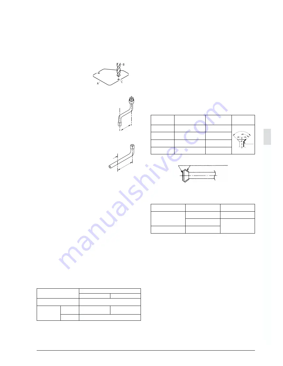
•
Remove the knock out hole by drilling the 2 concave recesses
with a Ø 6mm drill (see figure). Afterwards, paint the edges to
avoid rusting.
A Knock out hole
B Drill
C Concave recess
•
Liquid side:
Provide a liquid side pipe (field supply), and
connect it to the stop valve. Take care not to
allow it to touch the gas side pipe.
•
Gas side:
Cut the gas side accessory pipe and make connection using
an elbow (field supply).
A = cutting position
Operating stop valve: refer to figure 7
To open:
1. Remove the cap (1) and turn the shaft (2) counterclockwise
with hexagon socket screw keys.
2. Turn it all the way until the shaft stops.
3. Tighten the cap firmly.
To close:
1. Remove the cap and turn the shaft clockwise.
2. Tighten the shaft firmly until it reaches the sealed area (4) of
the body.
3. Tighten the cap firmly.
Note
-
Refer to the table for stop valve tightening torques.
-
Be sure to use both a spanner and a torque wrench when
connecting or disconnecting pipes to or from the unit.
-
Use a charging hose with push rod when using the service
port (5).
-
Check for refrigerant gas leakage after tightening the cap.
-
Make sure to keep the valve open during operation.
Precautions for connecting pipes
When the outdoor unit is installed above the indoor unit the
following can occur:
1. The condensated water on the stop valve can move to the
indoor unit. To avoid this, please cover the stop valve with
sealing material.
2. If the temperature is higher than 30
°
C and the humidity is
higher than RH 80%, then the thickness of the sealing
materials should be at least 20mm in order to avoid
condensation on the surface of the sealing.
•
Please refer to the table for the dimensions for processing
flares and for the tightening torques. (Too much tightening will
end up in splitting of the flare.)
•
When connecting the flare nut, coat the flare both inside and
outside with refrigerant oil (R22), ether or ester oil (R407C)
and initially tighten by hand before tightening firmly.
•
Make sure to flow nitrogen gas through the pipe when
brazing.
Great caution is needed when passing copper tubes through
walls.
In case of simultaneous operation system
•
Upward and downward piping should be performed at the
main piping line.
•
Use branch piping kit (optional) for branching refrigerant
pipes.
Precautions to be taken. (For details, refer to the manual
attached to branch piping kit.)
*1. Install the branch pipes horizontally (Maximum inclination:
20 degrees or less)
*2. Length of branch pipe to the indoor unit should be as short
as possible.
*3. Try to keep lengths of both branch pipes to the indoor unit
equal.
±
100mm
±
167mm
A
Stop valve tightening torques
R(Y)(P)200
R(Y)(P)250
980~1470 N•cm (100~150 kgf•cm)
1960~2450 N•cm
2940~3430 N•cm
(200~250 kgf.cm)
(300~350 kgf.cm)
Service port (5)
Valve cap (1)
Liquid pipe
Gas pipe
3920~4410 N•cm (400~450 kgf.cm)
R=0.4~0.8
45
° ±
2
90
°±
0.5
A
A dimensions for
processing flares (mm)
Flare nut tightening torque
Piping size
Flare shape
3270~3990 N•cm
(333~407 kgf•cm)
6180~7540 N•cm
(630~770 kgf•cm)
9720~11860 N•cm
(989.8~1208 kgf•cm)
12.0 ~ 12.4
18.6 ~ 19.0
22.9 ~ 23.3
Ø 9.5
Ø 15.9
Ø 19.1
Application of refrigerant oil
(for R407C ether or ester oil should be used)
•
Take measures against contamination when installing pipes.
Prevent foreign materials like moisture and other impurities
from mixing into the system.
Protection method
More than a month
Pinch the pipe
Outdoor unit
Indoor
Less than a month
Regardless of the period
Pinch or tape the pipe
Place
Installation period
4950~6030 N•cm
(504~616 kgf•cm)
15.4 ~ 15.8
Ø 12.7


